Feedback Control
Open Loop vs. Closed Loop control circuit
There are two ways of motor control: Open Loop and Closed Loop. In an open loop, the task of the system is to send electrical signals to the actuator to perform a certain action. Although the precise signals and commands are sent, there is no way built into the system to confirm if the actuator is truly in the desired position, speed etc., However, if the system comprises electronics which constantly provides feedback on the position and velocity of the actuator, then the motor control system is a closed loop. Feedback could be the number of revolutions per minute, angle of the shaft, etc. Operational control and feedback control combined together is a complete motion control system.
The graphical representation shows the difference between open and closed loop.
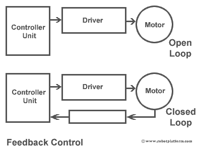
As shown in the image, both the systems contain a controller unit and a driver. However a closed loop has an additional feedback control which provides information on rotor position (shaft), velocity etc. Feedback control is mostly important in DC motors as it does not have any built-in control circuitry. However, the same feedback control can be implemented in other rotary actuators too.
There are different types of feedback controllers available. We will try to comprehend the most generally used feedback devices.
Shaft encoders / rotary encoders
These devices are most commonly used in DC motors. An encoder disk made of glass or plastic containing opaque and transparent areas is attached to the motor shaft. A light source (generally infrared light) passes through these transparent areas to read the disc pattern. This output is processed further in a controller unit which determines the speed, distance, revolutions and position.
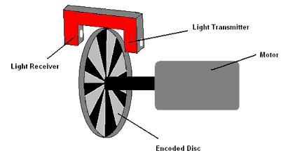
Rotary encoders come in different shapes and sizes. However, the working principle is almost the same and these devices can be used for precise information on speed, distance, revolutions and position.
Resolvers, proximity probes, pots are also widely used for measuring speed and distance. However, they are rarely used in robotics.
This completes a brief explanation on motion and motor controllers. In the next section we will discuss about microcontrollers which provides decision making power to our robots.
Do you have anything to say?
Visit the Forum to discuss, learn and share anything related to robotics and electronics !!


