Breadboard Tutorial
How do you make an electrical circuit? Create a path for electric current to flow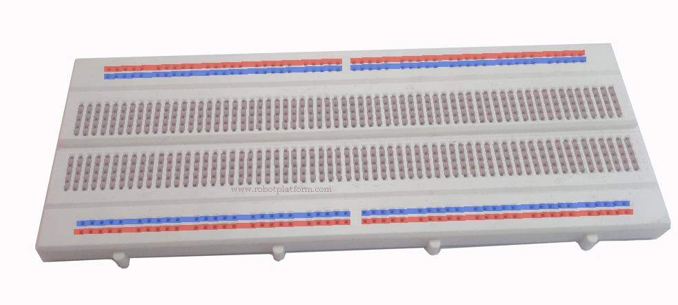 , provide a conducting source, and lastly a load. To create a path, we have several options. We can either solder all the components together, or take a wire and twist the parts together; if both seem impractical, we can use a breadboard. Each of these options has its own advantages and disadvantages. Twisting wires to the components is unworkable and clumsy if you have more than one or two components, though it is simple and easy. Soldering is the best option if you need to tie them all permanently and you have a known working circuit. Breadboard comes handy and useful when there is a need to build prototypes of electronics, or for experimenting.
Suppose you have a circuit diagram and need to test whether it works or not. Breadboard allows you to just plug the components inside in an appropriate manner and let the intelligence of breadboard designers do the rest.
What is a breadboard?
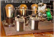 In the early days of electronics, copper wires or copper strips were nailed to a wooden board and components were soldered over them. The wooden board was most likely a wooden bread cutting board. Refer to the image of a radio manufactured over a wooden breadboard.
Over time, this bread-board evolved in design while retaining the same name. There are different breadboards available like optical breadboard, Perfboard, and what not. Here we are interested in an electronic solderless breadboard, also known as Protoboard.
Electronic Solderless Breadboard
Electronic solderless breadboard which is essentially called breadboard hereafter is a plastic block with tiny sockets or holes in it. These sockets contain spring like clips which are connected together with metallic strips in a defined path. The image shows a virtual path within a typical solderless breadboard. Leads of components are directly plugged inside these sockets and jumper wires are plugged in to connect these components. The center notch is designed to accommodate aDIP (dual in-line package) IC.
Breadboard Layout
Although breadboards come in different sizes, they almost share the same layout with two divisions; the terminalstrip and the bus strip.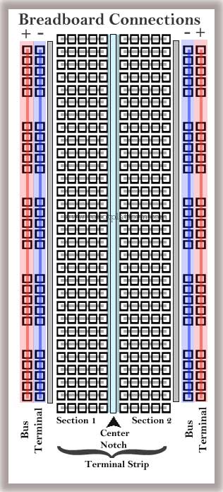
Terminal Strip
This is the main area where all components are plugged in. Usually this section is logically divided into two sections with a center notch dividing the two areas. As mentioned before DIP IC’s can be directly plugged in here. Interestingly due to the depth of the notch, they pass enough air through them acting as an additional cooling agent for the IC’s base.The bus area contains a series of rows with sockets connected on either side of the notch. The number of connected sockets will normally be limited to 5 in any row. In the figure, the gray connections in the Terminal Strip area represent connections between each hole / socket (click for an enlarged view).
Bus Strip
This area is utilized to power up the components in the breadboard. Bus strips are located on either side of the breadboard with two columns each, one for supply voltage and another for ground. You might also see breadboards where each side has only one columnand larger breadboard with multiple columns. The red area marked in the figure is to represent source voltage and blue area represent ground. However, you can interchange ground with source voltage as there are no hard and fast rules for that.
Tips & Precautions
- Make sure the jumper wires or component leads are not too tiny. If so, they might break a connection
- Use entire space in the breadboard rather than plugging all the components together and making it look ugly, and also difficult to debug
- If you are using an IC, start by plugging it first and then place other components around it
- Use smaller boards for simple projects. You can hook them up together if you need a bigger board for a bigger project. After all breadboards are for there for hooking up things together temporarily.
- Make the best use of inbuild metallic strips for connections rather than jumper wires
- Breadboards are current and voltage limited. Do not connect high voltage or current from your mains to a breadboard. Since the connections are too close, it might short and fry everything
- Breadboards cannot be used to mount SMD (surface mount technology devices) due to size limitation. You might still use an adapter, but they are an added cost
- Breadboard is limited to prototype simple and medium sized circuits. Large and complex circuits are unmanageable
- Not all components have suitable leads which can be plugged directly into a breadboard. One example is a Pot (Variable resistor). In this case, you need to solder a suitable single core wire and then plug in.
- Stranded wire should be avoided over a breadboard as it might spoil your breadboard. A tiny broken wire from a stranded wire is enough to take you on a roller coaster ride
Do you have anything to say?
Visit the Forum to discuss, learn and share anything related to robotics and electronics !!


