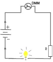
Current Measurement:
Sometimes it is very important to measure current to ensure if a circuit is operating as intended and also to check current consumption of various components. There are different tools available in the market which helps in measuring current. Some of them are Ammeter, Shunt resistor with a microcontroller, Current Clamp (usually for AC) etc. Since we are interested in a multimeter, we will see how we can utilize it for our requirements.
Measuring current is a bit tricky. You need to connect the multimeter in series with your circuit, or in other words break your circuit and let the current flow through the meter. The standard procedure to follow is to cut the leads (or remove the ones which have been soldered) and measure the current flow.
How do we do this? Move the knob towards current measurement marked as “A” (Ampere), followed by a hyphen with an underline (or DCA). Normal range provided in a multimeter is between 2000 uA (micro Ampere) to 200 mA (milli-ampere). Connect the red lead to the positive direction and the black lead to negative one with DMM knob moved to the highest range. Once you are confident that the connection is secure, power on your circuit. LCD displays a value in uA, or mA or Ampere, as per the measurement unit set in your DMM. Now turn the knob to a lower range until you get acceptable results.
Measuring higher current with a lower current range set can blow your DMM fuse, and also damage the circuitry within. If you need to measure higher currents, more than 200mA, then connect the red lead to port named 10A (or 20A, 30A if your multimeter supports). Move the knob to 10A (or more, if available) and measure it in the same way as described above. But be wary about the fact that it is unfused and unprotected. It might burn the leads and short or even end up in a fire. Safety first!!!
Do not try to gauge current from AC mains in your house as they are potentially lethal. If you are serious about it, consider using a current clamp.
Resistance:
Measuring resistance in a digital multimeter is as simple as it could ever be. Move the knob towards resistance marked as Ω (ohm) in the multimeter. Normally your multimeter should be labeled with maximum resistance reading. Choose the approximate resistance value or move your knob towards the highest resistance value. If the resistance is higher than the selected value, your reading displays 1. If the resistor value is lower then the value selected, then it displays a 0. Moving the knob to appropriate value gives you most accurate resistance measurement. Resistance is measured in Ohms.
However there are a few precautions while measuring resistance.
- Always turn off power before measuring resistance
- It is best advised to measure a standalone resistor rather than the one within a circuit, as other connected components may affect the reading
- In case you need to measure a resistor within a circuit, ensure that any connected capacitors are discharged.
Measuring resistance is as easy as eating a piece of cake. Move the knob, connect, read and analyze. In case you have an auto ranging multimeter, then it is much more easier. Just touch the resistor ends to the multimeter leads. After a couple of seconds (yes, they are a bit slower) they show you the reading.
This concludes a brief discussion on multimeter and its usage. Feel free to add your comments and queries in the forum.
Do you have anything to say?
Visit the Forum to discuss, learn and share anything related to robotics and electronics !!


