Numbering Systems - Decimal, Hexadecimal, Binary, Octal
Many numbering systems are used like Decimal, Hexadecimal, Binary and Octal. I will explain each one in detail and then get into Binary format which is the numerical system of interest.
Decimal: We are all unconditionally familiar with the decimal format. This is what you use everyday to count and calculate. This system uses ten symbols as representations which are 0 through 9 (0,1,2,3,4,5,6,7,8,9). Combining these symbols (digits) would allow you to count past 9. Suppose we write 52438906, then this number is nothing but a combination of digits from 0 to 9.
Let me introduce two more terminologies here. MSB (Most Significant Bit) and LSB (Least Significant Bit); in the number 52438906, 5 is the MSB which is the leftmost digit, and 6 is the LSB which is the rightmost digit. With this in mind, we always read digits from LSB (from right) towards MSB (towards left). The digits can be numbered or counted accordingly. i.e. 6 with a digit count 0 and 5 with a digit count 7.
| Number: | 5 | 2 | 4 | 3 | 8 | 9 | 0 | 6 |
| Digit Count: | 7 | 6 | 5 | 4 | 3 | 2 | 1 | 0 |
This numerical system is also known as base(10) numerical system. 52438906 is represented as 52438906(10) which means 52438906 base 10, or normally just 52438906.
Hexadecimal: Hexadecimal numerical system work in the same way as Decimal with the main difference being there are more symbols. The first ten are the same conventional 0 through 9. There are 6 new additions to this list which are A, B, C, D, E, and F (or alternatively a, b, c, d, e, f) which corresponds to 10, 11, 12, 13, 14 and15. This would make the list 0,1,2,3,4,5,6,7,8,9,A,B,C,D,E and F.
Suppose we take EE1F65 as an example, then E is the MSB and 5 is the LSB.
If we make a counting table for hexadecimal numbers, then it would look like be:
| Hexadecimal: | E | E | 1 | F | 6 | 5 |
| Decimal: | 14 | 14 | 1 | 15 | 6 | 5 |
| Digit Count: | 5 | 4 | 3 | 2 | 1 | 0 |
This numerical representation is known as base-16 written as EE1F65(16)
Hexadecimal to Decimal conversion:
The rule of decimal for mathematical representation holds good for hexadecimals too. To convert our example EE1F65(16) into decimal format, we can write as:

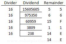
Decimal to Hexadecimal conversion:
Similarly, this number in decimal format can be converted into hexadecimal by taking the LCM of this number. (Least Common Multiple, remember school days?)

Hence the output is EE1F65(16)
Binary: Binary numbers are another set of symbols that are very easy for a machine to interpret (bewildering for humans). This is the most important format used in any digital system. “Bi” represents two, meaning there are only two symbols. They are 0 and 1. (Either ON or OFF). Binary digit is also commonly known as Bit. A set of four bits is called a nibble and a set of eight bits is called a byte. In this format, any number is represented as a combination of 0’s and 1’s. A counting table for binary numbers can be written as:
| Decimal: | 0 | 1 | 2 | 3 | 4 | 5 | 6 | 7 |
| Binary: | 0000 | 0001 | 0010 | 0011 | 0100 | 0101 | 0110 | 0111 |
| Hexadecimal: | 0 | 1 | 2 | 3 | 4 | 5 | 6 | 7 |
| Decimal: | 8 | 9 | 10 | 11 | 12 | 13 | 14 | 15 |
| Binary: | 1000 | 1001 | 1010 | 1011 | 1100 | 1101 | 1110 | 1111 |
| Hexadecimal: | 8 | 9 | A | B | C | D | E | F |
This representation is known as base-2 (or commonly binary) numbering system written as 1010(2)
If you observe carefully, I have represented each decimal as a nibble (set of 4 binary digits). All hexadecimal symbols can be represented as a set of 4 binary digits. Using this format makes us easy to understand and calculate as compared to understand and compute every single bit. Hence hexadecimal notation is normally used in electronics for electronic representation of numbers.
Binary to Decimal conversion:
The rules remain the same except that the multiplication factor will be 2 instead of 16. Suppose you have a decimal number 1100 1010(2). A digit count in the below table helps us to convert this set of binary digits to decimal number format.
| Binary: | 1 | 1 | 0 | 0 | 1 | 0 | 1 | 0 |
| Digit Count: | 7 | 6 | 5 | 4 | 3 | 2 | 1 | 0 |

Binary to Hexadecimal conversion: As discussed earlier, binary to hexadecimal is straight forward and simple. Split the binary number into nibble, a set of 4 binary digits. Now replace each nibble with the corresponding hexadecimal number as per the discussion above. Hence 1100 1010(2) would become CA(16). The same is true the other way around. You can split each hexadecimal digit and convert it into binary format where each digit is a combination of 4 binary digits (nibble).
What if we have only 3 binary digits like 101(2)? If you have anything less than 4 digits, add imaginary 0’s before the MSB to make it 4 bits. So, 10(2) will become 0010(2) and 101(2) will be 0101(2).
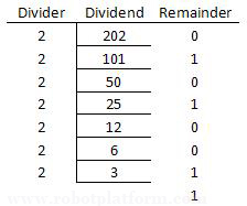
Decimal to Binary conversion: We repeat the LCM method with the only difference that the divider is now 2.

Octal: Unlike hexadecimal, this is a complicated notation used to represent binary numbers. This system has only 8 symbols, 0 through 7 (0, 1, 2, 3, 4, 5, 6 and 7). If you have already guessed it, then yes each octal value can be represented by only three binary digits where hexadecimal requires 4 digits. Octal format is rarely used today except for few UNIX systems. This representation is known as base-8 numbering system written as 1235(8)
This concludes number systems used in our digital world. In the next section, we will understand digital logic and logic gates. For those who missed reading the above theory, here is a table structure of number system.
| Decimal: | 0 | 1 | 2 | 3 | 4 | 5 | 6 | 7 |
| Binary: | 0000 | 0001 | 0010 | 0011 | 0100 | 0101 | 0110 | 0111 |
| Octal: | 0 | 1 | 2 | 3 | 4 | 5 | 6 | 7 |
| Hexadecimal: | 0 | 1 | 2 | 3 | 4 | 5 | 6 | 7 |
| Decimal: | 8 | 9 | 10 | 11 | 12 | 13 | 14 | 15 |
| Binary: | 1000 | 1001 | 1010 | 1011 | 1100 | 1101 | 1110 | 1111 |
| Octal: | 10 | 11 | 12 | 13 | 14 | 15 | 16 | 17 |
| Hexadecimal: | 8 | 9 | A | B | C | D | E | F |
Do you have anything to say?
Visit the Forum to discuss, learn and share anything related to robotics and electronics !!


