Continuity or Connectivity Test:
What is continuity or connectivity? Have you come across a situation when you know a joint has been soldered and it turns out to be not connected? Anytime a power cord looks strong and new from outside and broken from inside?
To check these flaws, we use one of the basic functionalities of a multimeter known as "continuity check". When two leads are electrically connected to each other, it means that the connection is continuous. To check for continuity, you need to first turn the DMM knob to continuity mode (some DMM's also double as a diode tester, and is called the diode mode). Now touch the tip of your DMM leads to the connection points on your circuit. If you hear a continuous beep, then it is continuous. Some DMM's do not have a buzzer and you need to look at the LCD to see if the numbers change from 1 to something weird. This weird number is the resistance between those two points which is shown only if they are connected. If you are sure they should be connected and do not hear a beep, or the number on the LCD does not change then I guess you have a faulty connection.
If you are interested to know what happens behind the scene, then here is the secret. The multimeter sends out a small amount of current to the lead and to the circuit; if the current reaches the second lead and back to the multimeter without any resistance (or minimal resistance), then they are said to be connected (also sometimes referred as connection is short).
Now you know how to check if the power cord is broken, or if any two wires are connected or not.
Points to remember:
- Before taking any measurements, cross check your multimeter for its accuracy. You can do a basic continuity test to confirm if it reads 0 when the leads are connected to each other.
- It is always good to power down your circuits before performing a continuity check
- Be careful while testing a circuit when there is a capacitor between the two points. If you know that two wires should not be connected and hear a beep sound, then check if a capacitor connects them.. If yes, then you might hear this beep until the capacitor drains. This happens because the capacitor has a small amount of current stored and makes it act like they the connected. Usually this is the case when you check continuity between GND and VCC.
- Switching leads will not change the values. i.e. if you test two points with black and red leads and then interchange to red and black, reading still remains the same.
Voltage Measurement:
Measuring voltage is to measure the potential difference between two points. Let us learn this with an example. You need only two things for this experiment:
- Multimeter (of course!!)
- Battery
Battery gives out Direct Current (DC), as compared to current in your mains which is Alternating Current (AC). Keeping this in mind, turn your multimeter knob towards DC voltage marked as “V”(Voltage) followed by a hyphen with a dotted underline (or DCV). Make sure you stop at a rating which is much higher than your expected battery voltage. This is simply to prevent overloading the multimeter and damaging it.
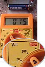
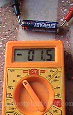
 Now assuming that you have not changed the DMM leads from their port after the connectivity tutorial, (if in doubt, visit the connectivity section and reread it) connect the red lead to the positive side of the battery and black lead to negative side of the battery, and see the numbers displayed on your DMM LCD. Those numbers are nothing but your Voltage measurements. Suppose, if it shows a value of "1.5", then the voltage of this battery is 1.5 Volts. Repeat this process with all those batteries available with you. You can also try measuring the voltage in your mobile charger / laptop adapter.
 Try reversing the connection by touching the tip of the black lead to positive side of the battery/charger, and the red lead to the negative. What did you see? Does it show a negative value? Yes, keep in mind that polarity is very important while measuring voltages.
Similarly you can also test your circuits too. But you need to power up your circuit to measure the voltage, unlike the previous continuity test.
Did I hear you asking if voltage from the mains in your home can be measured? Of course, yes. However I would advise you to be very cautious while working with AC due to its high voltage.
Points to remember:
- There are few DMM’s which provide autoranging facility. This means that you do not need to worry about overloading. Once you shift the knob to a measuring unit (Voltage / current /resistance), the multimeter adjusts itself to a required range. However there are complaints that they are sluggish, and the better ones are quiet expensive
- Some DMM's have different modes to get to DC voltage and AC voltage. Check your manual to avoid surprising results
- Turning the meter knob to a range which is lesser then the expected range would show 1, which means that the measurement is not within your selected range
- If you do not know the voltage required for a DC circuit under test, start with the highest value and then decrease until you get acceptable results.
Do you have anything to say?
Visit the Forum to discuss, learn and share anything related to robotics and electronics !!


