Combining Capacitors
Combining components is nothing new. Just like resistors, even capacitors can be combined in series, or in parallel. Suppose there is a set of capacitors connected together and we need to calculate the total charge, then we need to identify a pair of capacitors which are either in series, or in parallel and find the total charge they can store. Then replacing a capacitor with this charge, we can move on to the next capacitor in the set. To calculate total charge of a pair of capacitors, either in series or in parallel we have few formulas to make life simpler.
Capacitors in Parallel
This combination is the simplest among the two. When capacitors are connected in parallel, then the total capacitance is the summation of all individual capacitors connected together.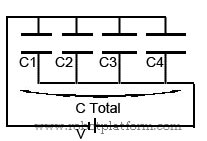
How does this work? One plate of each capacitor is directly connected to source voltage. This means total area of plates connected to source voltage is more, which can be visualized as more plate area connected to voltage. If you remember, more plate area leads to more capacitance. Hence if capacitors are connected in parallel, capacitance increases.
Suppose you have four capacitors C1, C2, C3, C4 connected in parallel, then the total capacitance is
CTotal = C1 + C2 + C3 + C4
This equation is similar to resistors connected in series formula.
However, when you connect different capacitors with different voltage ratings, do realize not to exceed supply voltage more than the lowest voltage rating of any capacitor connected. i.e. if voltage rating of C1 is 16V, C2 is 24V, C3 is 24V and C4 is 16V, then the least voltage rating is 16V. So, do make it a point to maintain supply voltage less than 16 volts.
Capacitors in Series
This is an odd combination. There might be little reason to use this combination unless you need to add more capacitors to reduce capacitance. Capacitors are connected in series by connecting second lead of a capacitor to the first lead of another capacitor. That is, positive plate of a capacitor is connected to negative plate of another capacitor in case of polarized capacitor.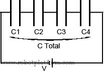
How does this work? Assume that you have two capacitors, one with plate spacing X (dielectric width) and another with plate spacing Y. When you connect them in series, you are actually increasing the spacing between the plates. Now the overall spacing of connected capacitors is X + Y. That means you are increasing the spacing between the plates and reducing its capacitance by connecting them in series.
But you do not need to know plate spacing, distance, blah, blah of each capacitor. If you know the formula to calculate value of resistors connected in parallel, then you already know how to calculate capacitance of capacitors connected in series.
CT = 1 / (1/C1 + 1/C2 + 1/C3 … 1/Cn), where CT is total capacitance and C1 through Cn are capacitors connected in series.
1/CT = 1/C1 + 1/C2 + 1/C3 … 1/Cn
However, if your circuit contains only two capacitors, then the equation is much simpler.
CT = C1 x C2 / C1 + C2
To make it much simpler, if your circuit contains two and only two identical capacitors connected in series, then CT = ½ C, where C is capacitance of any individual capacitor.
Tutorial index:
Do you have anything to say?
Visit the Forum to discuss, learn and share anything related to robotics and electronics !!


