Making of Photoresistor sensor
Output from photoresistors can be directly fed into a microcontroller’s Analog-to-digital converter pin. Just solder a resistor to one of the two leads and connect three wires to three outgoing pins; one for Vcc (or Vin), one for ground and the third one to your microcontroller. I have also given you a step by step guide to solder a resistor and connecting wires and make two photoresistor sensors.
Parts required: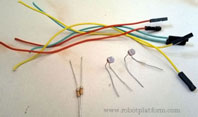
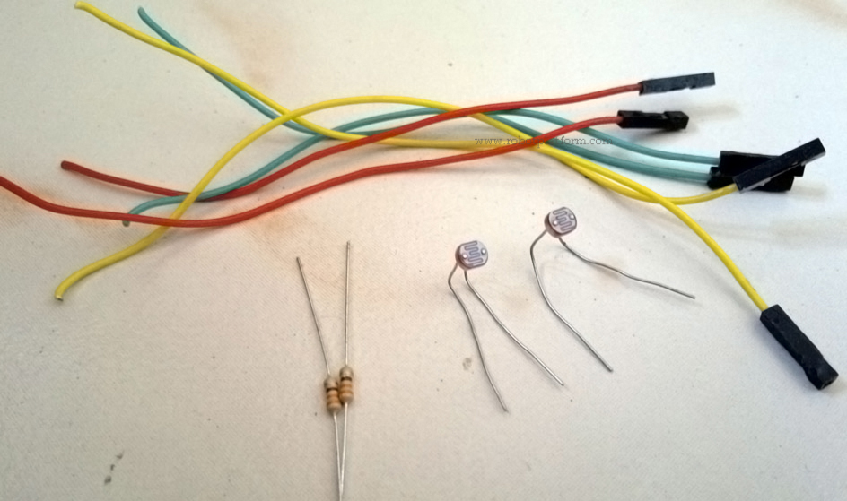
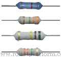
- Photoresistors / LDR's
Photoresistors / LDR's : 2 - Wire with connectors
Wire with connectors : 6 - Resistor
Resistor : 2 (1.5KΩ to 2KΩ) - Soldering Iron / Solder gun
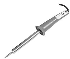
Solder Iron - Solder / Solder Lead
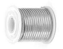
Solder Lead - Duct Tape
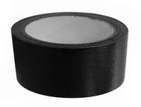
Duct Tape
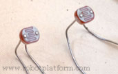
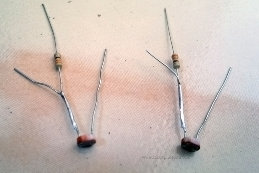
Solder a 1.5KΩ resistor to one of the leads of photoresistor as shown in the image (As usual, click on the image for an enlarged view). Photoresistors are sturdy and can take enough heat from the soldering iron. But do not overdo it in such a way that you fry it. Also solder the resistor a few millimeters away from the tip or face of photoresistor and avoid bending the leads near the tip. Be cautious not to burn your fingers as the leads heat up very fast.
Note: I have used a 330Ω resistor in these pictures which were used for a different purpose altogether, but the procedure remains the same.
Now solder there wires with connectors to the three leads coming out of the photoresistor; two from Photoresistor and one from the resistor. Needless to say those connectors are there to make life easier while connecting to a circuit board. If you need to plug them to a breadboard, then you need male connectors plugged into a breadboard.
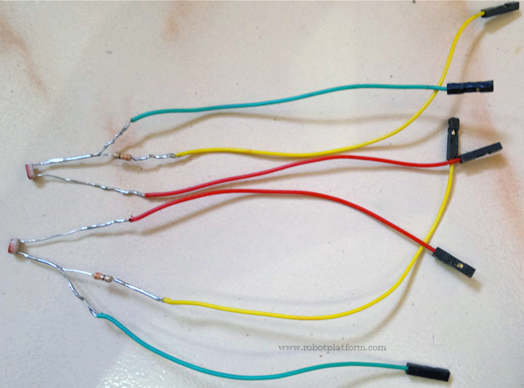
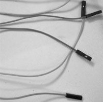
You are almost done. However as a safety measure, I normally prefer insulating these exposed leads. A cheap alternative is to use duct tape. If you have a heavy wallet or want your connections to look more professional, you can use heat shrink and cover up these exposed wires.
As for me, I carefully wound duct tape for all the three wires separately. As a side note, it is always advisable to use a different colored wire for identification.

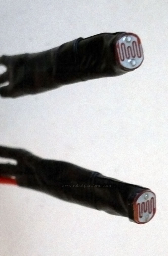
You may not want to do this, but I like it this way. I wound duct tape a couple of more times to ensure they look like the one shown in the figure. This makes it easier for me whenever I keep it on any of my robot chassis.
Calculating resistor value:
1.5KΩ resistor selected in this sensor is not exactly true in all cases. Since each photoresistor can be different from the other, it is difficult to judge what value would suffice your needs. Hence I would suggest you to calculate resistance required for your individual LDR's and connect it accordingly.
Calculating resistance is quick and simple. Find the resistance of your LDR using a multimeter by pointing it to bright sunlight, or a fluorescent bulb and note down the result (say R1). Now cover the photoresistor completely and measure resistance (say R2). To calculate resistor value we need to find the square root of the product of these two resistances.
i.e: R = sqrt (R1 x R2)
You may not find a resistor with exactly the same value (R), but not to worry you can choose the next higher available value and solder it across.
If you are too lazy to pick up your calculator for this, I have a calculator here for your ready reference. Enter R1 and R2 and click calculate.
LDR Resistor Calculator (uses javascript)
That is it with the Photoresistor Sensor tutorial. Make one, connect it with your microcontroller analog pin and have fun.
Do you have anything to say?
Visit the Forum to discuss, learn and share anything related to robotics and electronics !!


