Multimeter Tutorial

A multimeter is one of those nifty devices which anybody working on current and voltage should own. If you don’t have one, go out and get it for a few bucks, or borrow it from a friend. If you say you can work without that, pray to your electric and electronic gods and connect your circuit. *puffff… and smoke...*
After all, what does it do? It is a convenient measuring device which provides combined functionality of a voltmeter - to measures voltage, an ammeter – to measure current, and an ohmmeter – for measuring resistance. It is also used to check continuity within a circuit
There are two variants in a multimeter. An analog multimeter and a digital multimeter;
Analog multimeter: Analog multimeter long existed, and now a the thing of the past. In the heart of an analog multimeter lie a magnet and a coil, arranged in such a way that when current passes through it, a needle mounted over it moves from its initial position towards the other end. Amount of current on the coil decides movement of the needle. Usually they are powered by the circuit under test, except for resistance measurement which is powered by the battery within the unit.
 Digital multimeter: Almost all the functionalities of an analog multimeter is available in a digital multimeter.These pocket sized gadgets are here to stay and provide additional functionalities then their analog equivalents. They are powered by their own batteries and least impact the circuit under test. I would suggest you to buy a digital multimeter (commonly known as DMM), which is easy to use, cheaper then an analog multimeter, and gives you more precise results.There are hundreds of manufactures who sell their own version of DMM, ranging from a few dollars to thousands. I would not suggest you to go and buy the costliest one available in market, but a good one with basic functionalities is required.
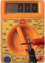
 DMM’s look complicated on their first glance, with those red and black wires, a knob and those printed numbers, LCD display etc., Once you understand how they work, it is much easier to use them. In this tutorial, I have chosen a basic multimeter for demonstration, and all available versions roughly work the same way. Let us start by plugging those wires, and later learn how to use it.
A typical DMM has three to four ports. First plug in the black lead (also known as probe) to the port marked as COM (short for Common). The red lead can be connected to other ports based on the measurements we need. For now, connect it to port marked as “VO”, or in some devices, marked as “Input” or “VOmA”. Switch on your device, or turn the knob (or dial) and see the LCD switching on. Don’t bother which way you turn it. The LCD is where you see numerical values to read the measurements. It also doubles up to alert you for any warnings, or show measurement units.
Turn the multimeter knob until it points to an icon on the DMM which resembles a sound wave (or a “speaker-on” symbol). This mode is termed as continuity mode (or diode mode). Observe the LCD value changing to “1” (1 means that the resistance between them is infinity) (or “OL” - short for Open Loop in some devices). Hold the black and red leads and connect their tip. You will hear a continuous beep, and the numbers on the LCD change and end up to "0". The sound is due to a piezo buzzer within the DMM.Now your multimeter is all set, and if you are ready to read further, scroll down. Else go, have a drink and come back.
The following are few functionalities of a multimeter which anyone woking on electronics should know. We will discuss each one in detail.
Do you have anything to say?
Visit the Forum to discuss, learn and share anything related to robotics and electronics !!


