Dual H-bridge Motor Driver - L293D IC
Building the circuit - Part II
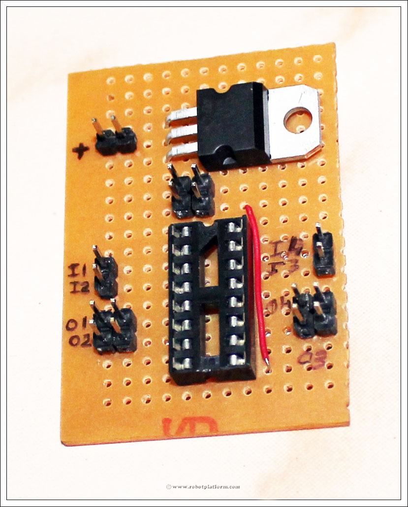
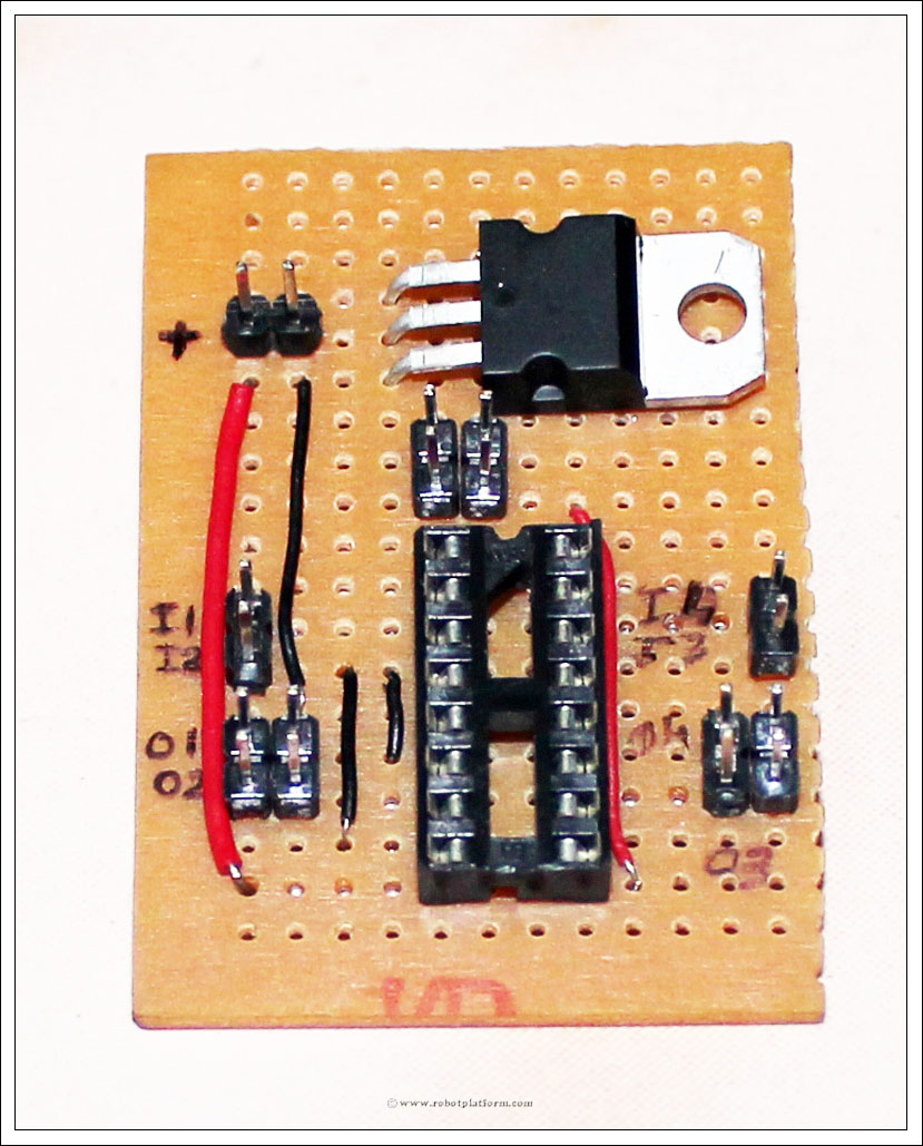
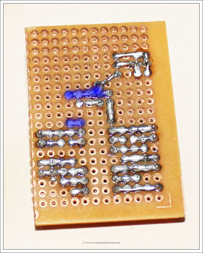
Add a red wire (or any color) to connect Pin9 to enable pin. Push one side of the wire next to Pin9 and the other side to a hole above the socket (as shown below). I have used a marker to mark the pins to avoid confusion.
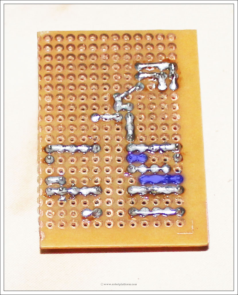
Solder the pins and wires carefully as mentioned below:
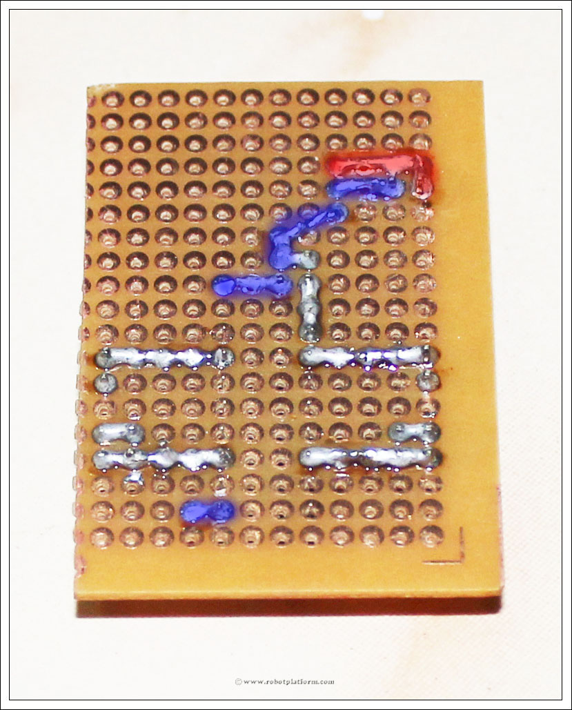
- Solder one side of the wire to Pin9 (Click to enlarge the image. The bottom highlighted part)
- The other side of the wire will be soldered to second pin of enable header
- Vout from regulator (bottom lead) is soldered to header above enable pins
- Gnd from regulator (middle lead) is connected to left power pin (left pin if the copper side of board is on top)
- Vin from regulator (top lead) is connected to right power pin
I have highlighted Vin in RED just to make sure you do not solder ground and power pins together. If you do connect, you will end up shorting the circuit and frying it.
Add a red wire running from positive of power pin to Pin8 of the socket.
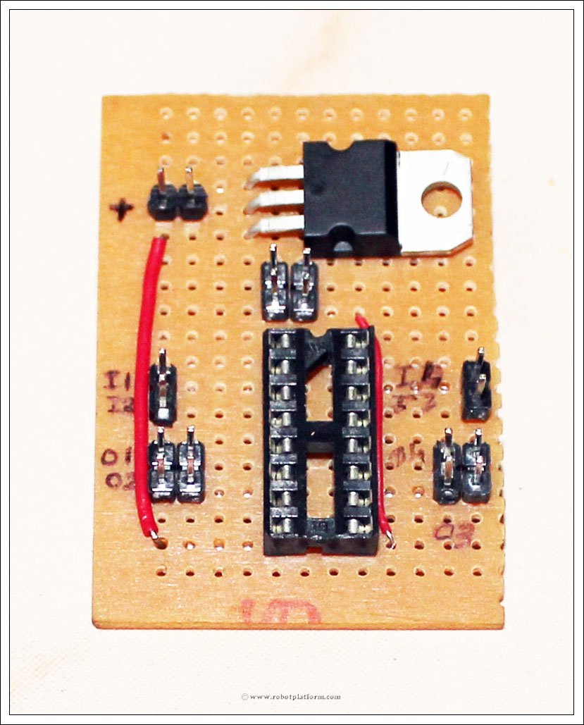
Solder one end of red wire to positive of power pin and the other end to Pin8
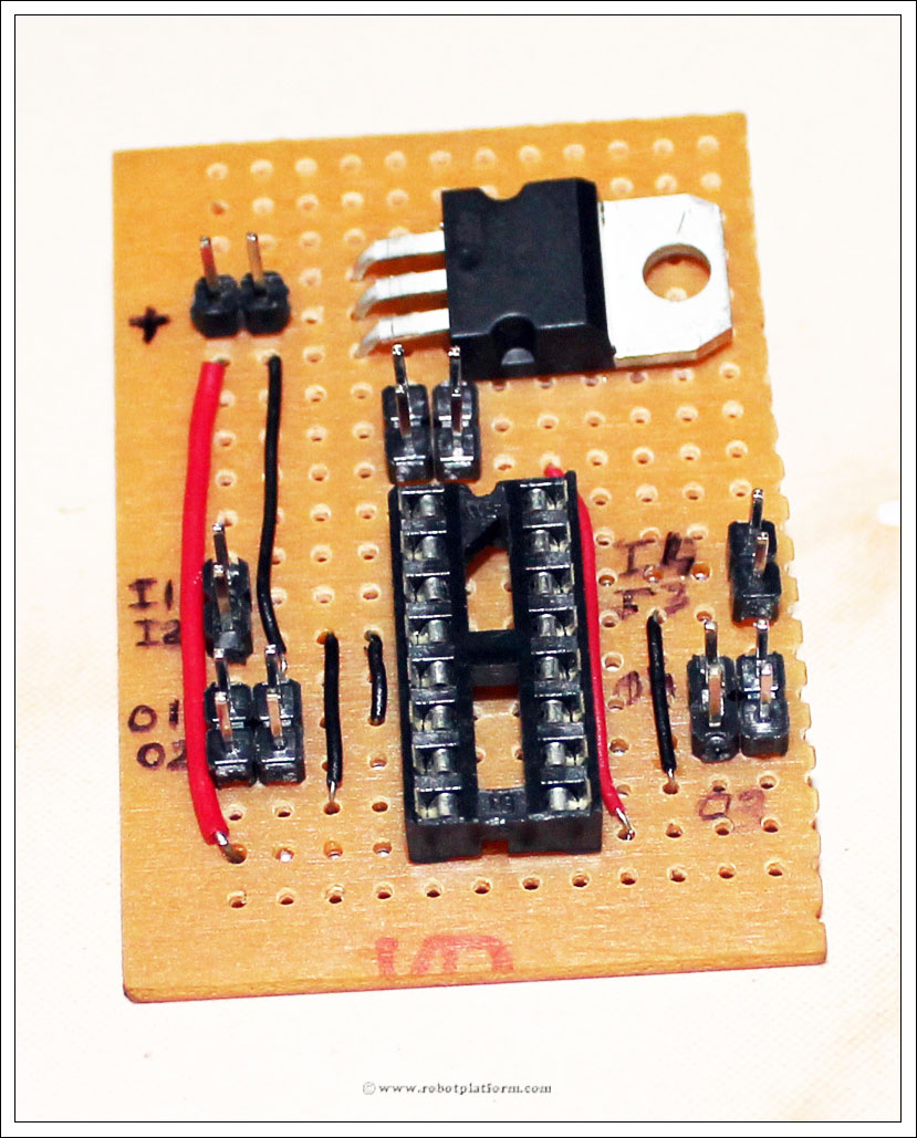
Add another black wire to connect ground. Push one end below the ground of power pins and the other end next to Pin4 of the socket

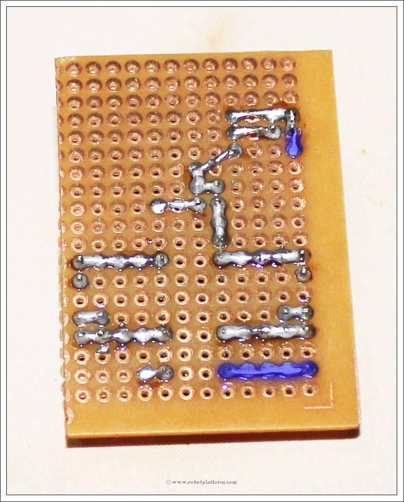
Solder the black wire as shown here. One side connects ground of power pins and other side connects Pin4.

Cut and trim a small wire and place it in two holes next to Pin3 and Pin5 of the socket.

This wire connects output1 of L293D IC to header pin. Solder top side of the wire to Pin3 and bottom side of the wire to first output header pin on the left. (marked O1)
Add a slightly larger black wire next to previously added black wire such that the top end of the wire is in the same row of the black small wire, but the bottom end is two holes next to Pin7 of the socket.
Solder the top side of this wire to second pin of input header (marked I2) and solder the bottom end to Pin7 of the socket.

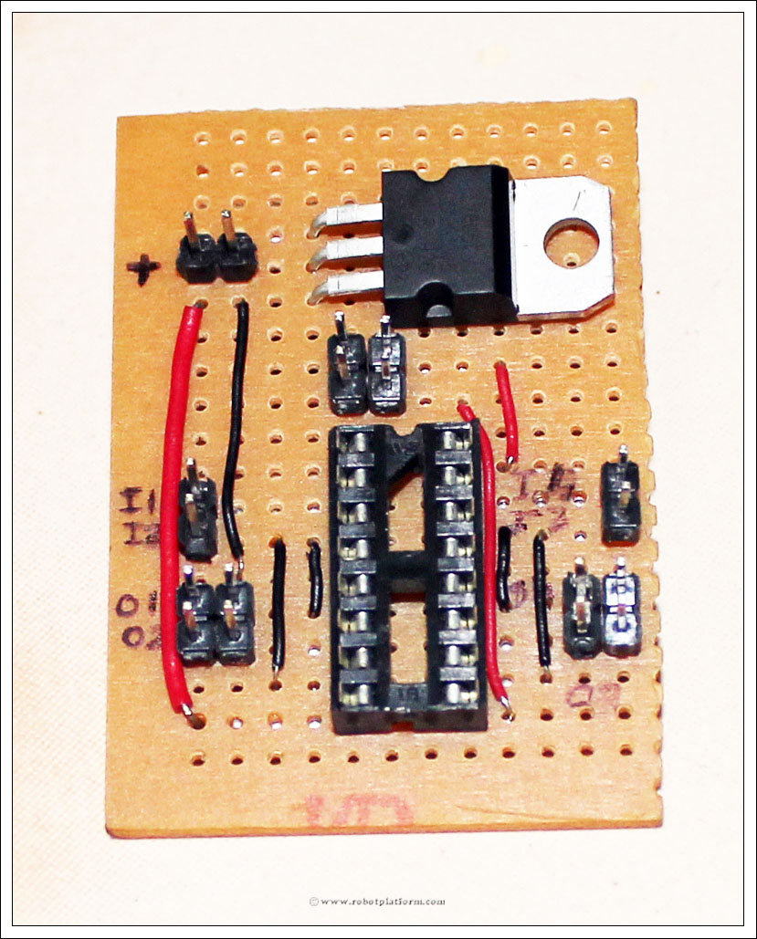
Add a similar wire to right side of the board as shown in the image. The top end of the wire should be pushed next to Pin14 and bottom end next to Pin10 of the socket. This connects input pin of IC to right input pin (marked I3)
Solder top end of the wire to header pin (marked I3) and bottom end to Pin10.

You are almost done!! Push the top end of a wire into a hole next to Pin14 and the bottom end next to Pin12 of the socket.

Solder the top end to Pin14 of the socket and bottom end to right output header pin (marked O4)

Since we need to power the components inside the IC, add a red wire which connects +5V to Pin16 of the socket. The two pins above enable pins are already connected to +5V and we can push one end of the wire to a hole next to that and other end next to Pin16.
Solder Pin16 to bottom end of the wire while top end of the wire is soldered to header pins above enable pins, which is further connected to Vout of regulator.
Lastly, solder all four ground pins together. Pin4, Pin5, Pin12 and Pin13 are all ground pins; solder them together.

DONE!! You have a completed (and hopefully working) L293D motor driver board which can control two motors.
As you can see in the image, I have drilled four holes (actually five including one below the regulator) and pushed four screws into it.
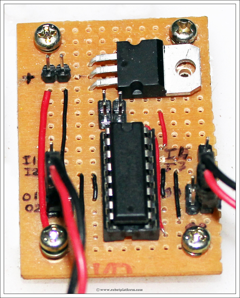
Whenever you implement it, always remember that enable pins are not connected. Either connect enable pins to your microcontroller pins and programmatically set it high, or use a jumper and connect each enable pin to the header just above it (which is connected to +5V)
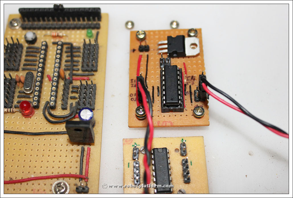
Here is the implementation on one of my robots. You can also see that there is another small board which is also a motor driver, but the board is built using PCB etching method.
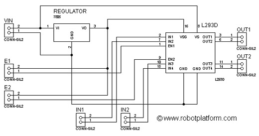
Here is the schematic I had developed. If anybody is interested in building a board using PCB Etching method, or any other method, please request in the forum and I will share the complete board designs.
Tutorial index:
Do you have anything to say?
Visit the Forum to discuss, learn and share anything related to robotics and electronics !!


