ADC in Atmega8 – Summary
If you have directly jumped to this section, then for a detailed explanation on ADC read this tutorial from the beginning. To summarize whatever we learnt till now:
 Signals are set of values that convey information and are measured by any independent attribute like time or space. Analog signals are real world signals around us like sound and light. Digital signals are analog equivalents in digital or numeric format which are well understood by digital systems like microcontrollers. ADC is one such hardware which measures analog signals (Voltage) and produces a digital equivalent of the same signal.
ADC in AVR devices uses a technique known as successive approximation by comparing input voltage with half of reference voltage generated internally. The comparison continues by dividing the voltage further down and updating each bit in ADC register by 1 if input voltage is high, 0 otherwise. This process lasts 8 (for 8 bit ADC) or 10 (for 10 bit ADC) times and generates resulting binary output.
With regards to Atmega8 a few concepts to know beforehand are:
- AVCC: This AVR pin supplies power to ADC. AVcc must not differ more than ± 0.3V from Vcc
- AREF: Another AVR pin which can optionally be used as an external voltage reference pin.
- Voltage Resolution: This is the smallest voltage increment which can be measured. For 10 bit ADC, there can be 1024 different voltages and for 8 bit ADC, there can be 256 different voltages.
- Input voltage can be measured as: VIn [V] = (ADCH*256+ADCL) * VRef [V] / 1024 for 10 bit ADC
- Input voltage can be measured as: VIn [V] = (ADCH)* VRef [V]/256 for 8 bit ADC
- Hardware units like DAC (Digital to Analog converter), Comparator, SHA or S/H (Signal and Hold), SAR (Successive approximation register) together complete AD conversion.
- Most AVR microcontrollers have built in ADC which reduces cost and space for an external ADC
- Lastly, be informed that all ADC pins are connected to only one internal ADC, which means you need to do one conversion at a time.
ADC Setup using Atmega8
If you are already dizzy with the boring theory, then wake up; we will start some programming. If you are not aware of bits, ports and programming, I recommend you to read AVR basics and complete blinking LED project before you start this, because Port basics and programming basics are not part of this tutorial.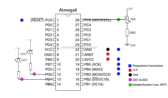
In this simple ADC project, we will set up adc in single conversion mode with 10 bit precision, complete a conversion and switch on and off two LED’s based on the result
If you have already completed blinking LED project, then you already have all the parts required for this project. One more component which adds to the list is a variable resistor / pot. The image in the right tells you how and what to connect. Click on it for a pictorial representation of connections.
We will write a Pseudo-code for this project and then implement corresponding C code for the same.
Determine ports and pins for LED and ADC
Configure LED Ports and Pins
Setup and enable ADC
While forever
Start ADC conversion
If ADC is high, turn on LED1 and turn off LED2
Else turn on LED2 and turn off LED1
End while
First, we will include header file io.h for this project
#include <avr/io.h>
Next, we will define two macros to ease our work of switching off and on the LED’s
#define PORT_ON(port,pin) port |= (1<<pin)
#define PORT_OFF(port,pin) port &= ~(1<<pin)
With these two in place, we will create a framework for our program:
#include  <avr/io.h>
#define  PORT_ON(port,pin) port |= (1<<pin)
#define  PORT_OFF(port,pin)  port &=  ~(1<<pin)

int  main(void)
  {
  unsigned  int adc_value; // Variable to hold ADC  result
  DDRD=0xff;	// Set PortD for LED output
  PORTD  = 0x00;	// Clear PortD Pins
  	//	Todo: Setup and enable ADC
  	// 		While forever
  	//		Start ADC conversion
  	//		If ADC is high, turn on LED1 and turn off LED2
  	//		Else turn on LED2 and turn off LED1
  	//		End while
  }
The next task is to configure ADC hardware
ADCSRA = (1<<ADEN) | (1<<ADPS2) | (1<<ADPS0);
// ADEN: Set to turn on ADC
//ADPS2: ADPS2 and ADPS0 set to make division factor 32
By setting ADCSRA in this way, we are turning on ADC and configuring division factor. If you are unsure on this, go back to ADCSRA Register section.
Now we need to set reference voltage. Here we will use external Aref voltage and turn off internal reference voltage. To do this, we need not write any extra code as REFS1 and REFS0 bit are cleared (0) by default. For more information, refer ADMUX tutorial.
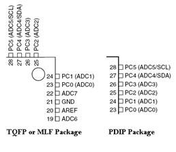
Now select the pin which will be used as ADC input channel. Let us select PC5 in atmega8.
ADMUX=0x05; //Binary equivalent of 0101
If you need to use free running mode, then set ADFR bit. Again, if you need 8 bit precision, we can set ADLAR bit to 1. Since we are using single conversion with 10 bit resolution, we will not write any extra code here. This completes ADC setup and we will start the conversion.
To start a conversion, we need to set ADSC bit in ADCSRA register
ADCSRA |= (1<<ADSC);
Rewriting our above code:
#include  <avr/io.h>
#define  PORT_ON(port,pin) port |= (1<<pin)
#define  PORT_OFF(port,pin)  port &=  ~(1<<pin)

int  main(void)
  {
  	unsigned  int adc_value;	// Variable to hold ADC  result
  	DDRD=0xff;	// Set Port D for LED output
  	PORTD  = 0x00;	// Clear PortD pins
  	// Set ADCSRA Register with division factor 32
  	ADCSRA  = (1<<ADEN) | (1<<ADPS2) | (1<<ADPS0);
  	ADMUX=0x05;	//Binary equivalent of 0101
  	while (1)	//Forever since it is in  single conversion mode
  	{
  		ADCSRA  |= (1<<ADSC);
  		// wait until conversion  completes; ADSC=0 means Complete
  		while (ADCSRA &  (1<<ADSC));
  		adc_value = ADCW;	//Store ADC result
  		//  Todo: Set and toggle LED status
  	}
  }
If you observe carefully we have used ADCW which is not found in Atmel datasheet. This is a compiler help which stores values of ADCL and ADCH. If we do not use this, then individually ADCH and ADCL should be polled. Also note that if we are using free running mode, then we need to check ADIF instead of ADSC as ADSC will never be zero in free running mode.
Now, all we need is to turn on and off LED’s to check the result. Since we use 10 bit mode, we can use values from 0 through 1024. If ADC value is less than 512 then LED1 should be turned on else LED2.
Our complete code will now be:
#include  <avr/io.h>
#define  PORT_ON(port,pin) port |= (1<<pin)
#define  PORT_OFF(port,pin)  port &=  ~(1<<pin)

int  main(void)
  {
  unsigned  int adc_value;	// Variable to hold ADC  result
  DDRD=0xff;	// Set Port D for LED output
  PORTD  = 0x00;	// Clear Portd pins

 	ADCSRA  = (1<<ADEN) | (1<<ADPS2) | (1<<ADPS0);
	// Set ADCSRA Register with division factor 32

  ADMUX=0x05;	//Binary equivalent of 0101

  while (1)	//Forever since it is in  single conversion mode
	{
  	ADCSRA  |= (1<<ADSC);	// Start conversion
		while (ADCSRA &  (1<<ADSC));
		// wait until conversion  completes; ADSC=0 means Complete

  	adc_value = ADCW;	//Store ADC result
		if (adc_value < 512)
  	{
  	PORT_OFF(PORTD,6);	// Clear 6th bit
  	PORT_ON  (PORTD,7);	// Set 7th  bit
  	}
  	else
  	{
		PORT_ON(PORTD,6);	//  Set 6th bit
		PORT_OFF  (PORTD,7);	// Clear 7th bit
  	}
  }
 }
To test this, connect a 10K variable resistor to PC5 as shown in the image.
Connect two LED’s with resistor to PORTD, pin 6 and pin7 (PD6 and PD7)
Turn the pot and see the result of your hard work, if at all you have tried making this.
This completes our ADC tutorial. If you have any issues in making this work for you, or any questions related to ADC, then direct it in the forum. You can download the compiled C code, make file along with .hex code here.
Tutorial index:
Do you have anything to say?
Visit the Forum to discuss, learn and share anything related to robotics and electronics !!


