Motor Speed Control
Brushed DC motor Control
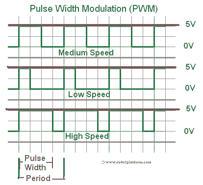
Torque in a brushed DC motor is directly proportional to the driving current. To control the speed of a DC motor, its torque is modulated using SCR (Silicon-Controlled rectifier) or PWM (Pulse Width Modulation). SCR’s and other methods are rarely used in robots and the widely accepted technique for speed control is PWM (Pulse Width Modulation). Imagine PWM as switching on and off a switch at a very fast pace. The longer the switch is ON, the higher the voltage is sent to the receiver creating greater speeds. Image shows a graphical representation of PWM.
H-bridge
Controlling a motor involves controlling the speed and rotation (either clockwise or anticlockwise). For DC motors, direction control is achieved by an H-bridge which drives the motor in either direction. Of course there are other means, but we will settle with the best known method. A typical H-bridge consists of a minimum of four solid state or mechanical switches; the graphical representation of H-bridge resembles the letter “H” and hence the name “H-bridge”.
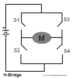
This simple circuit shown above can be used to drive the motor forwards, reverse, brake, or free-run by switching S1, S2, S3 and S4 on or off as per the below table.
| S1 | S2 | S3 | S4 | Motor |
| 1 | 0 | 0 | 1 | Clockwise (Forwards) |
| 0 | 1 | 1 | 0 | Anti-clockwise (Reverse) |
| 0 | 0 | 0 | 0 | Free run |
| 0 | 1 | 0 | 1 | Brake |
| 1 | 0 | 1 | 0 | Brake |
For small robots, you can either construct an H-bridge with a combination of PNP and NPN transistors, or purchase a package like L293x IC. There are different varieties of H-bridge packages available with additional components based on the requirement.
Servo Motor Control
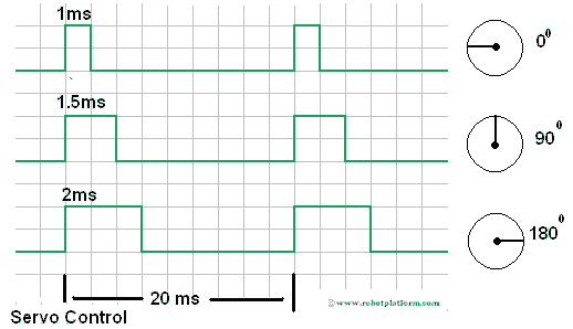
Rotation of a servo motor is controlled by sending different pulses to the servo controller. A typical servo is controlled with three wires: Power, Ground and Control. A pulse is sent to the servo every 20 milliseconds and an active high-pulse 9 which is generally between 1 and 2 milliseconds) determines the angular position of the motor. In the graphical representation, the lower limit is shown as 0° and the upper limit is shown as 180°. Based on the manufacturer, the upper limit can be 90°, 120°, 135° etc. Irrespective of the design, the central position is almost always achieved by sending a high pulse width of 1.5ms.
This unique design of a servo helps in controlling both the position and direction of the motor.
Stepper Motor Control
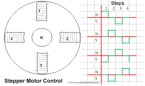
Stepper motor contains multiple electromagnets which rotates the motor shaft when energized. By sending desired pulses to these electromagnets, the direction and speed of a stepper motor can be controlled. In the image below, there are four electromagnets which control the rotor’s rotation. Activating each one of them in a desired fashion moves the rotor shaft to a particular position. The speed at which the pulses change determines the speed of the motor and the combination of powering the electromagnet decides the direction of the rotor.
Motor controllers can only send signals to control motor speed, but cannot assure that the motor is running at that exact same speed. In the next section, we will identify the different ways to check if motor is running at the speed expected.
Do you have anything to say?
Visit the Forum to discuss, learn and share anything related to robotics and electronics !!


