Programmer connections over Breadboard
Let us get these components together on a breadboard, and connect them. Refer to images and click on them for an enlarged view.
Plug the microcontroller into breadboard as shown in the figure.
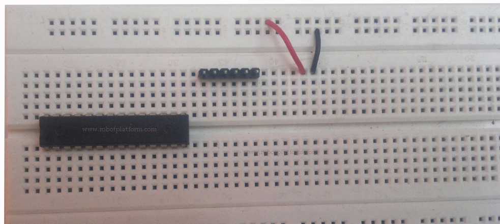
Leaving one row below the microcontroller connection, plug the male header in the next five sockets/holes.
Finally connect any two wires into the breadboard bus, which can later be used to connect LED.
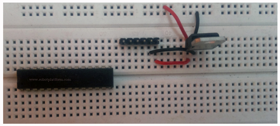
Plug the Voltage regulator (7805), which has three leads into the breadboard as shown here. Voltage regulator is very important to safeguard your microcontroller. When you connect source voltage (more than 5 volts) to the regulator, it provides regulated 5 volts output. Connect a black wire to Ground, Red wire to Output as shown in the figure
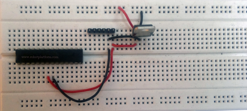
To power up the microcontroller, connect Red wire to Pin 7, which is 5 volts and black wire to Pin 8 of the microcontroller. You can directly connect these two wires to the regulated output from the regulator. I have used additional two wires just for clarity.
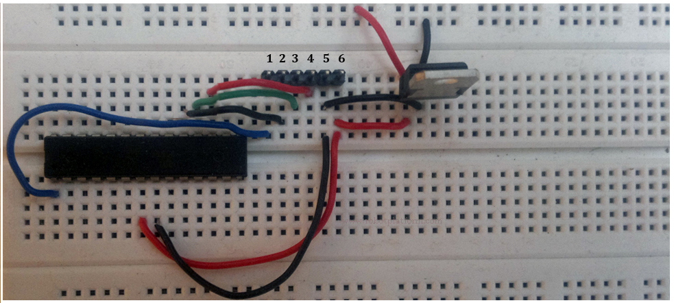
Now connect leads from Male header to Atmega8. I have numbered the male headers from 1 to 6 for your reference. Connect header-2 to pin-19 (PB5) of Atmega8. (You can connect the wire to any hole in the row where Pin-19 of µc controller is plugged). Connect header-3 to pin-18 (PB4) of µc, and then pin header-4 to pin-17 (PB3) of the microcontroller. Lastly, to connect your programmer to reset pin, connect header-1 to pin-1 (PC6). This completes your programmer connection. As a result, you have completed connections from SCK (PB5), MISO (PB4), MOSI (PB3) and RESET (PC6) in the respective order.
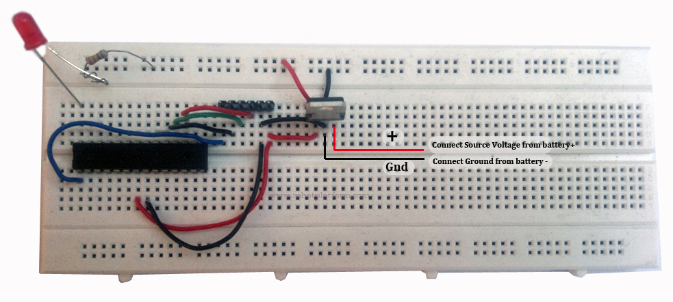
You are done with programmer connections. Connect a 6 or 9 volts battery to regulator as shown in the figure. Positive (+) of your battery should go to pin 1, negative (-) of your battery to pin 2 of regulator. Now plug in your programmer into the header and you are ready to program. Observe carefully and connect the pins in the same order as given here. If you are using any other programmer, check the pin details in that programmer and connect them to the header accordingly.
Tutorial index:
Do you have anything to say?
Visit the Forum to discuss, learn and share anything related to robotics and electronics !!


