PCB Etching tutorial
Removing toner from board
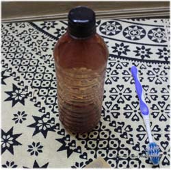
Now that the board is ready, you need to remove the toner lying over the copper tracks. Most acetone and alcohol based products can help you remove it. Thinner / acetone are widely used for removing toner. The bottle shown in the image is “thinner” generally used by painters. It is a clear liquid which evaporates quickly when exposed.
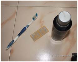
As an experiment, I used deodorant (which is usually alcohol based) and a tooth brush to remove the toner from the board. It might take a bit of work to rub off print, but works great.
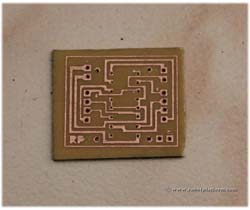
The printed circuit board is ready. As you can see, the board has come out exceptionally well. If in doubt, use a multimeter and check connectivity between track’s end points.
Drilling
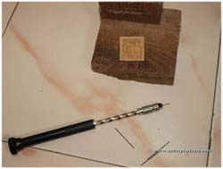
If you using through hole components, you need to drill holes into the board. In this tutorial, I have used a hand driller to drill circular holes into the board. Bits are attached to a drill and when the top part of the drill is pressed, the drill rotates creating a torque and axial force making a hold in the board.
I use 0.5 mm drill bits for mounting IC’s and 1mm drill bits for male / female headers. Since the bits are tiny, they can easily break when drilling. If you are lucky enough to own a drill motor, then drilling is much simpler.
Since I had two circuits printed on a single board, I had to cut the board into two.
Make sure you keep the PCB on a wooden frame to avoid any damage to the drill bit and the base. In the image, you can see a hand driller and those tiny drill bits lying around.
The drilling is complete and I have a professional looking circuit board. The final chore is to add the components and solder them.
Tutorial index:
Do you have anything to say?
Visit the Forum to discuss, learn and share anything related to robotics and electronics !!


