AVR Development board, Step-by-Step-Tutorial
How to build an Atmega8 development board
Adding an Electrolytic Capacitor
We will now add an Electrolytic capacitor to the board which is a two-lead capacitor that offers high level of capacitance per unit volume. Electrolytic capacitor is used to filter or reduce electrical noise and also power your circuit during short power drops from your battery (or any other power source). These capacitors have positive and negative polarity and hence take care to not connect the wrong leads.

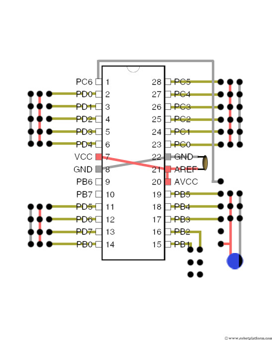
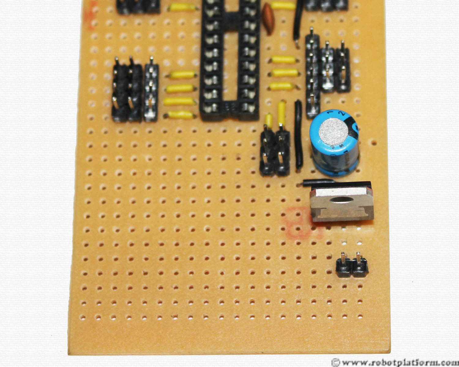
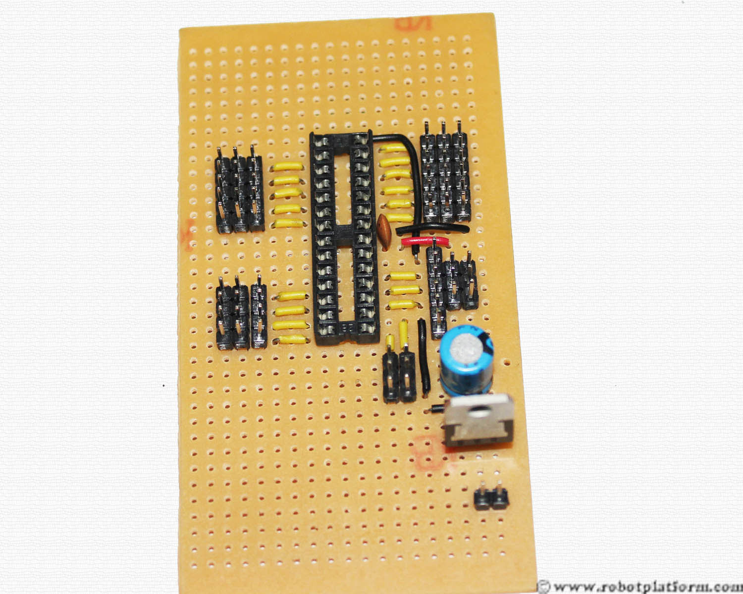
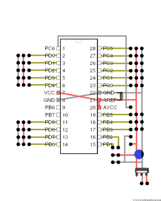
Plug the capacitor exactly as shown. The negative lead of the capacitor is pushed to the right side of the board (the column with the rightmost headers) and the positive lead to the left of that (which is used as positive bus).
Generally positive lead of the capacitor will be slightly longer than the other. Another marking is that the side with a negative lead will have a black strip on the capacitor and marked (as shown in the image).
I have added a Philips 100µF (micro farad), 25 Volt capacitor. If you already have a capacitor with different voltage, use them. Just make sure that the capacitor rating is much larger (at least twice) than your batteries voltage.
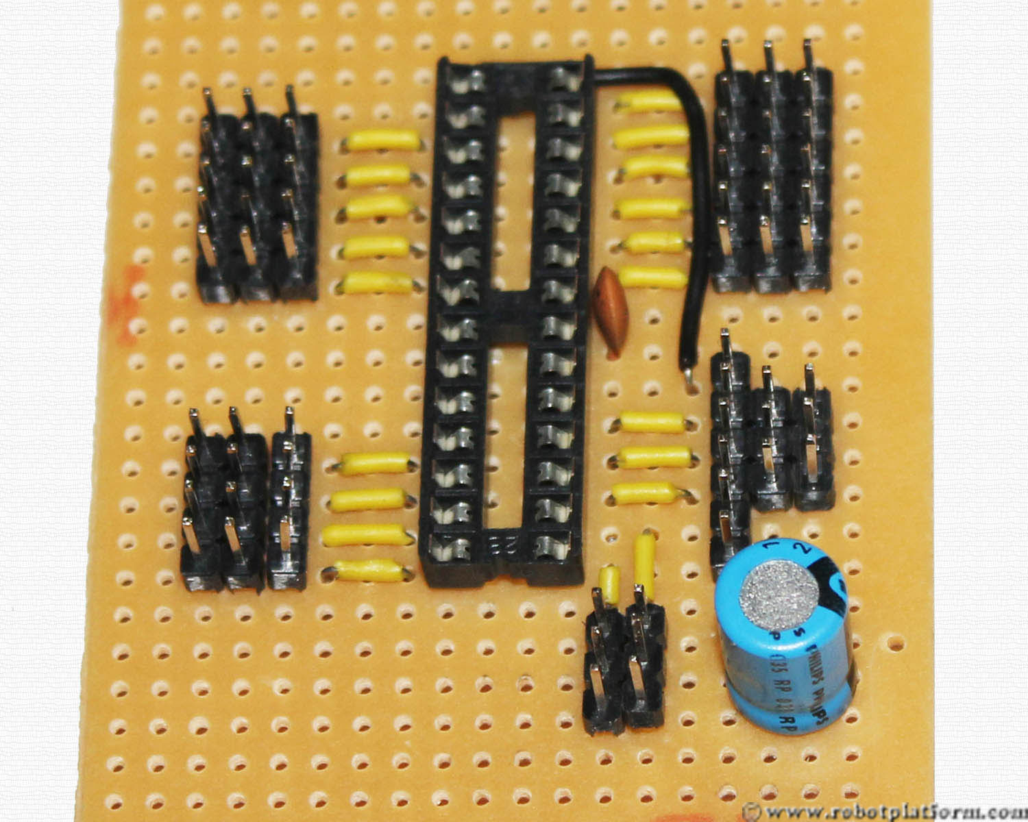
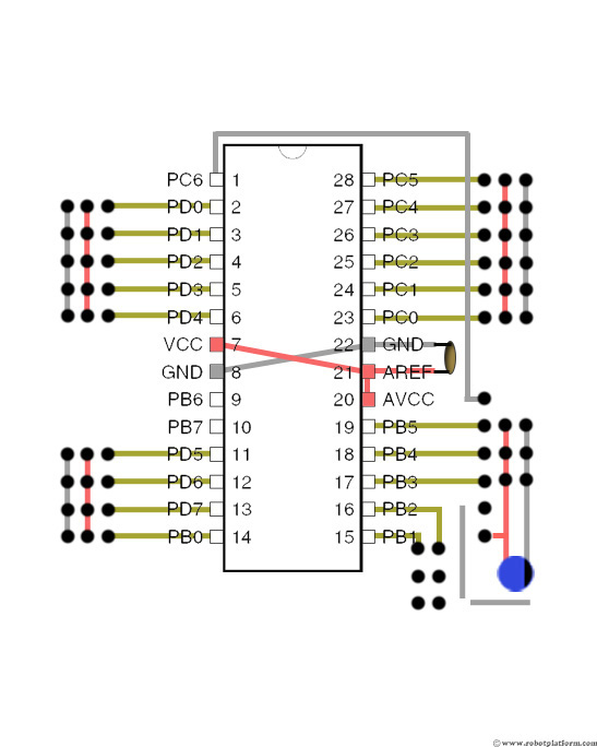
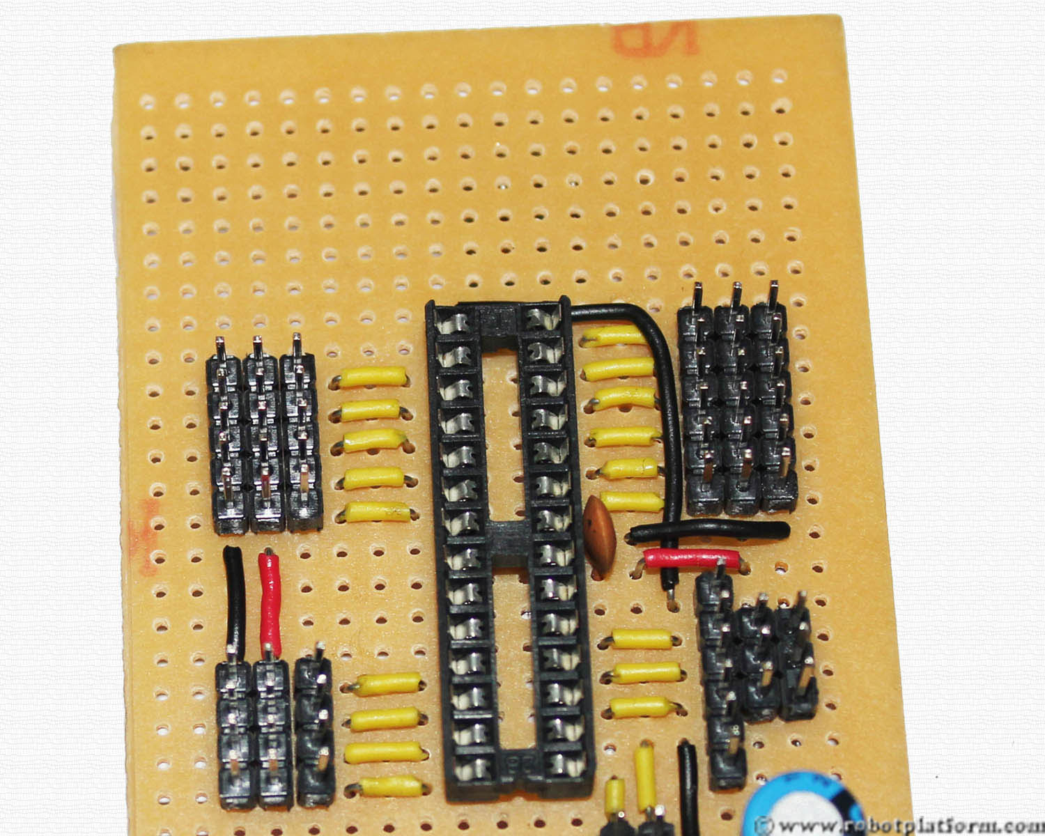
Bend the capacitor leads to connect the headers as shown.

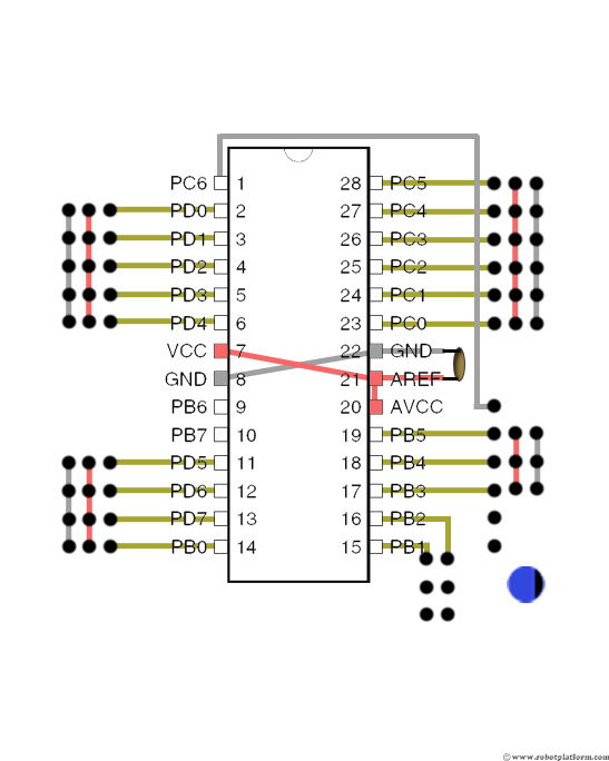
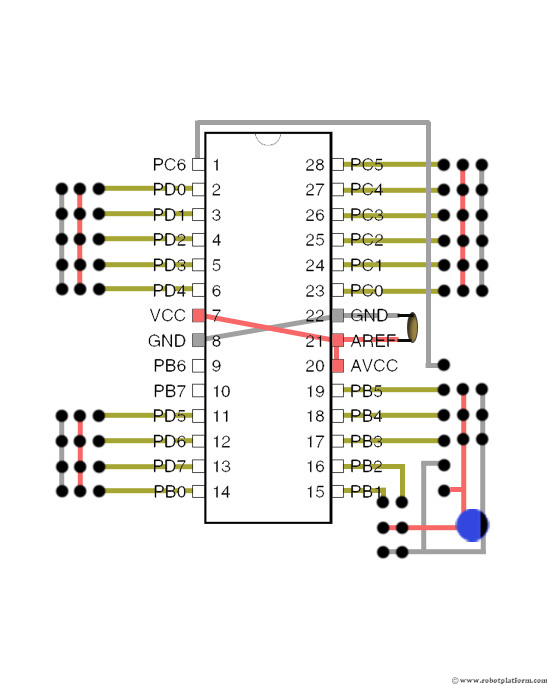
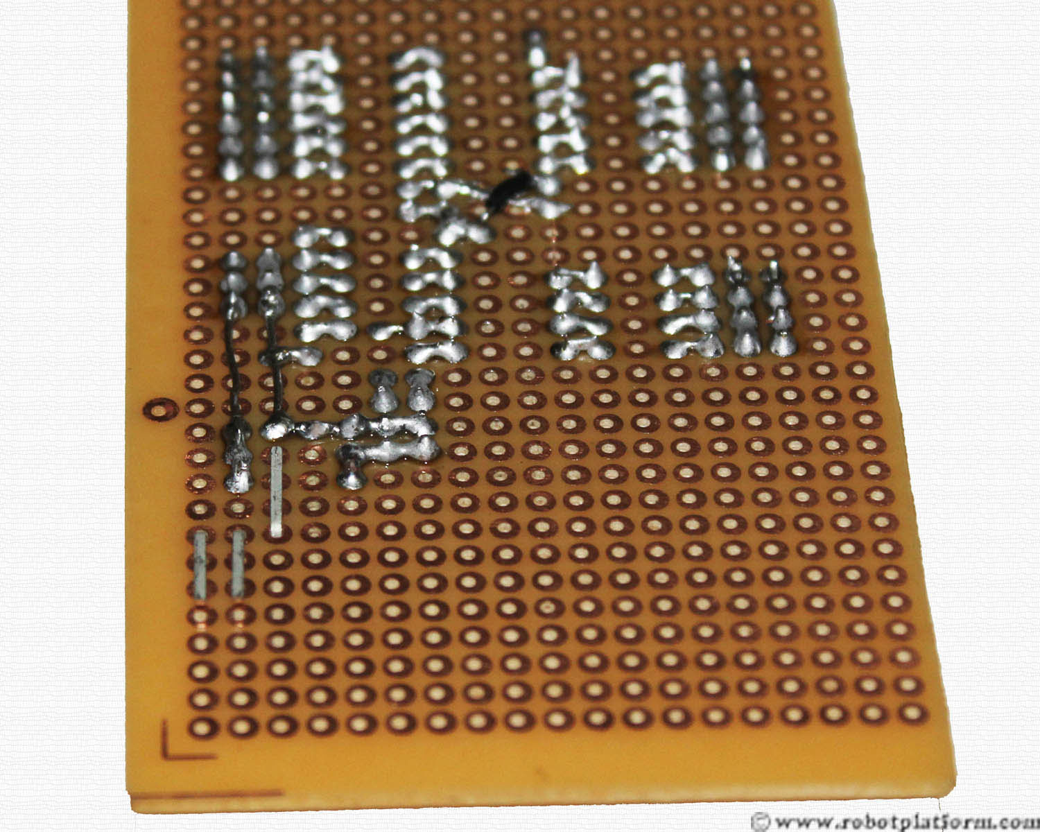
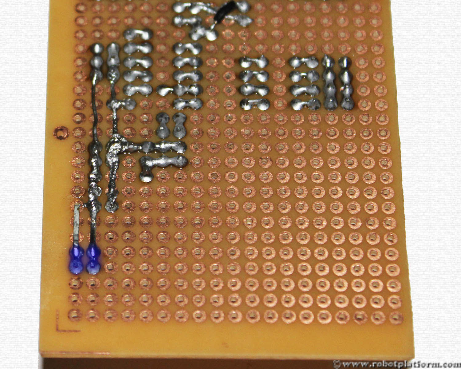
Solder the last pin in the programmer header to positive line of the capacitor.
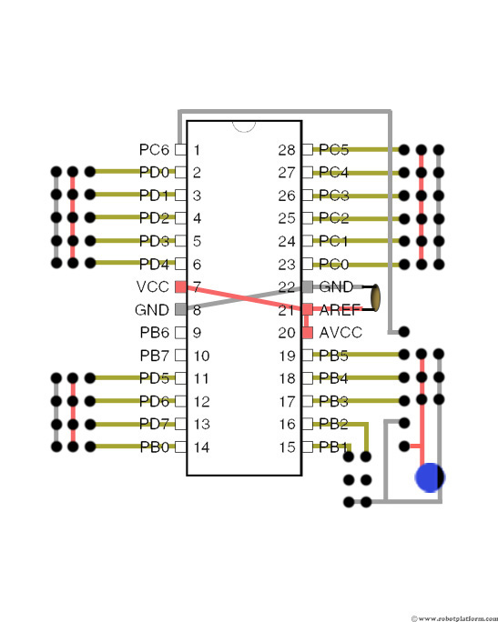
Add two more black wires, one ground line to pins PB1 and PB2 and the other for the programmer.

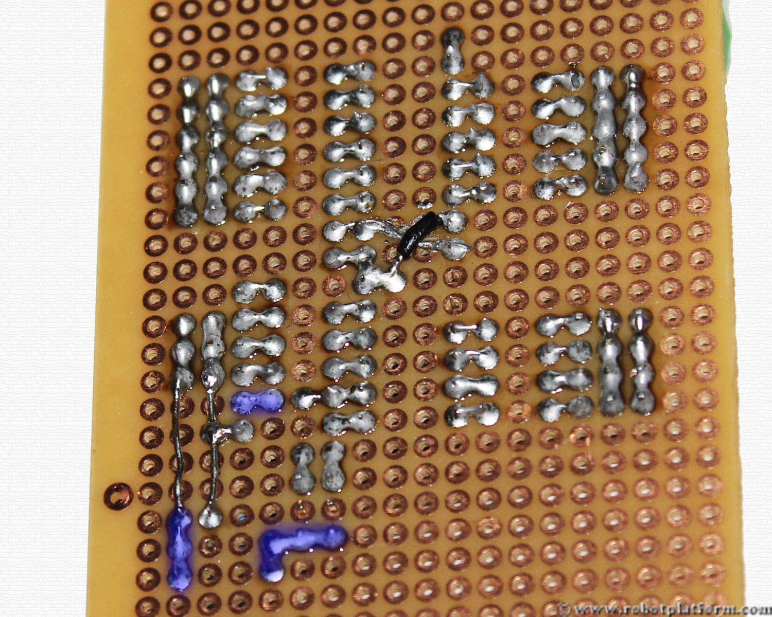
Observe how the wires are carefully bent. The ground of capacitor, the headers and the ground of programmer should be connected.
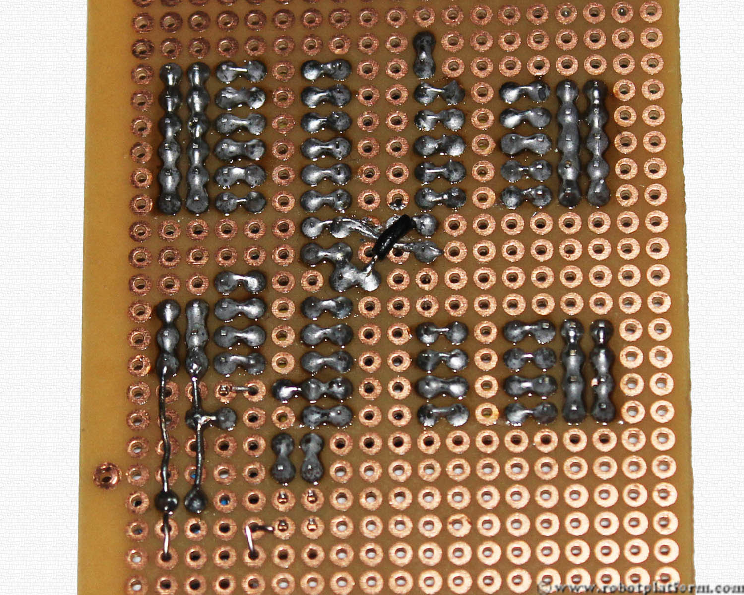
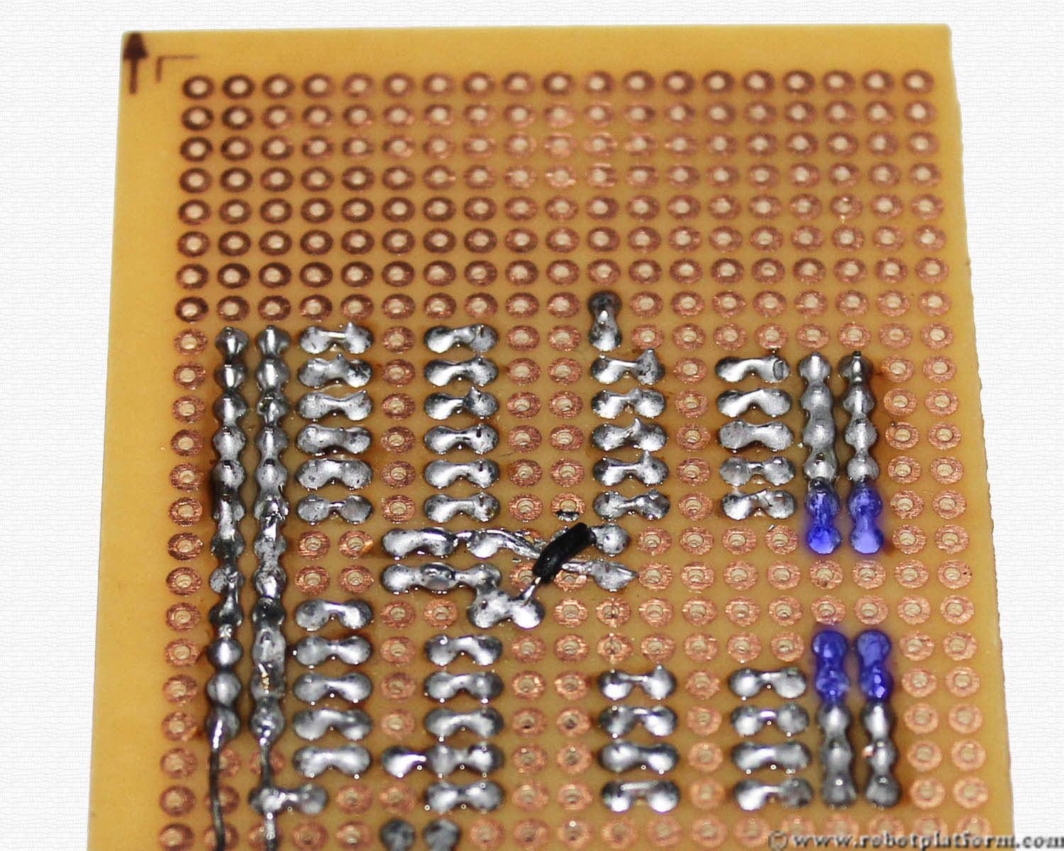
Solder the wires, header pins and capacitor lead as shown in the image.
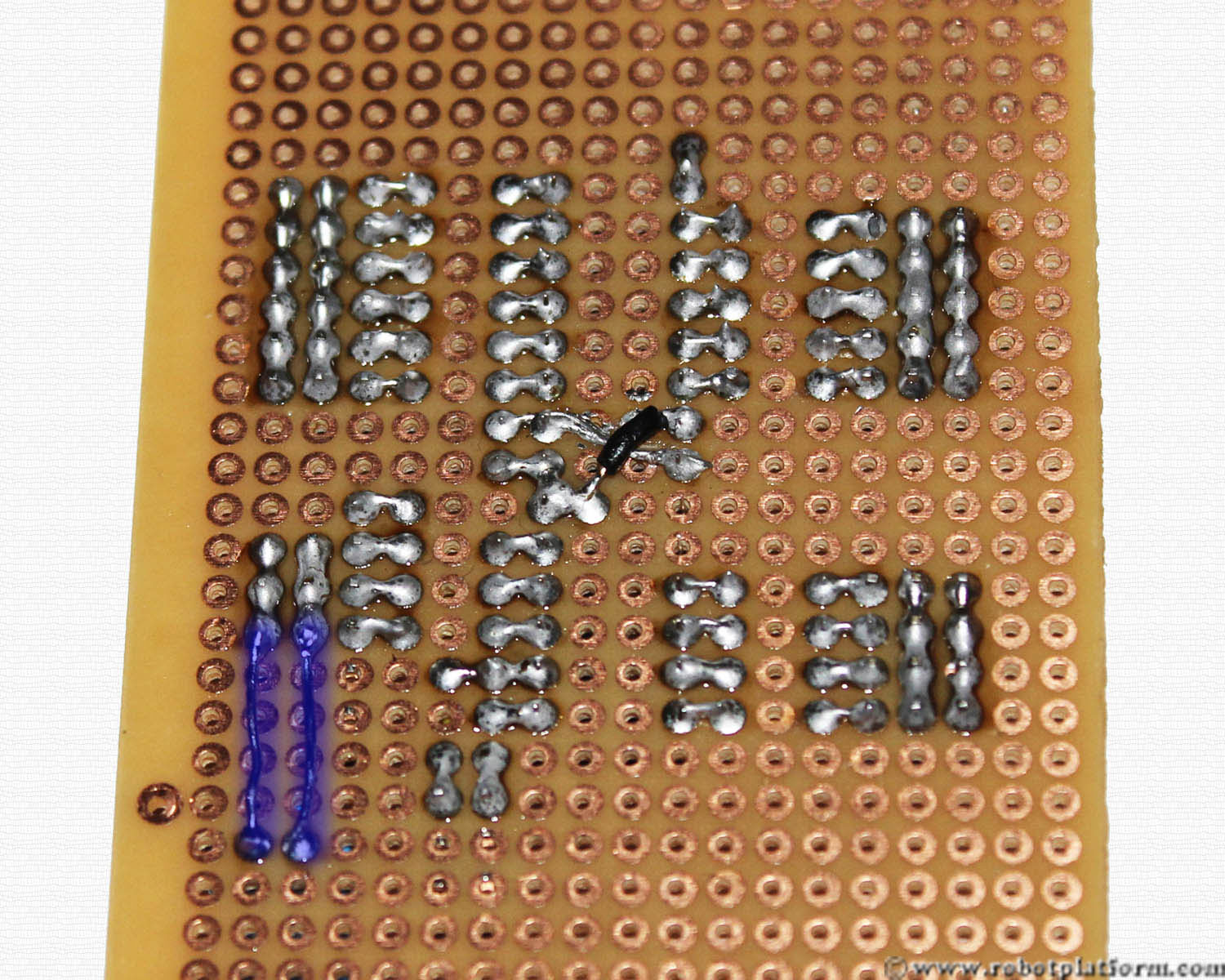
Now solder the power line of capacitor to PORTB header

Below the capacitor we will add a voltage regulator. As the name says, voltage regulator regulates the input voltage so that the output can be used to maintain a constant voltage. Our microcontroller requires a constant 5V input and the reason we have used a three pin LM7805 voltage regulator.
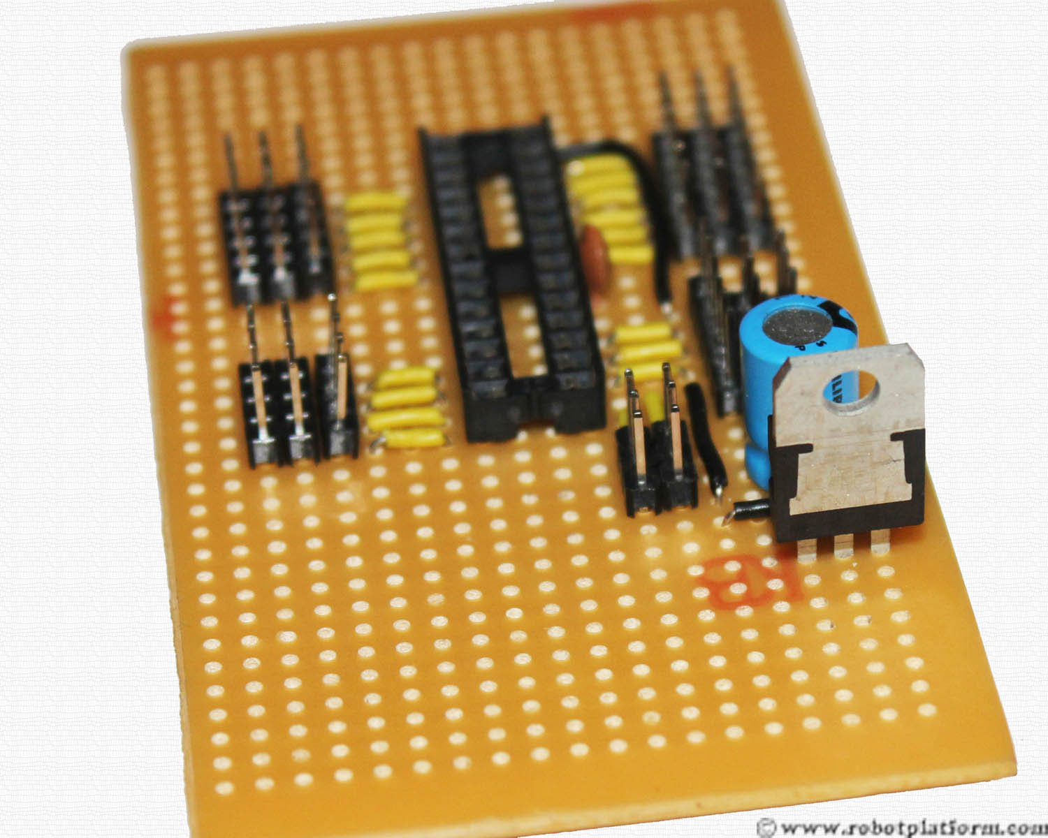
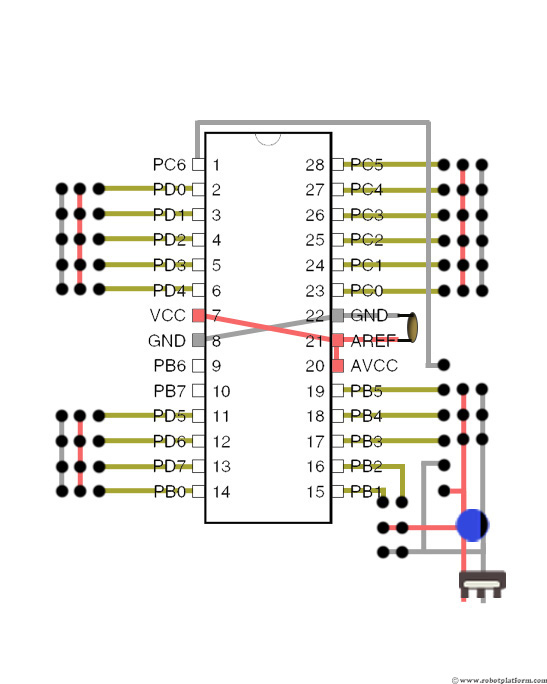
Voltage regulator has three pins. With the pins down and the metal side towards you, the left side is the regulated 5V (Vout), center pin being ground (Gnd), and the rightmost is the input voltage (Vin) which goes to batteries positive side. Vin should be in the same column as the power line of your board and ground in the same column as ground line.
Bend the regulator leads as shown in the image. Vout should be bent towards the top side of the board and the other two pins backwards.
Solder ground line of regulator to ground line of board, and Vout to power line of the board.
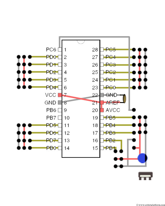
Add a two pin header in such a way that one pin is in line with Vin of regulator and the other in line with regulator’s ground pin.
Solder the header pins and the regulator pins. This header is used to connect your battery that powers your circuit.
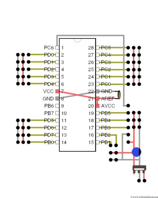
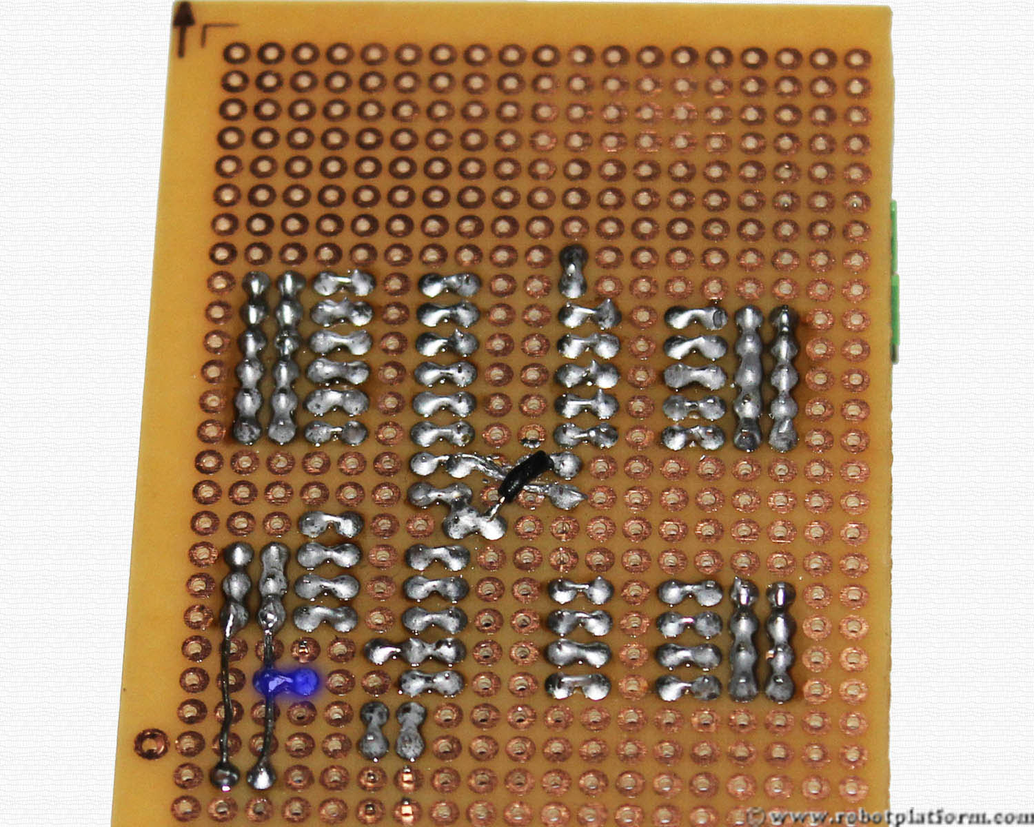
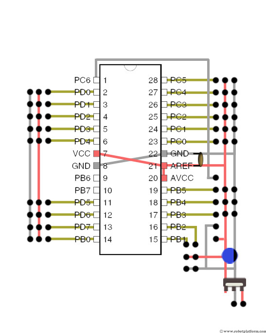
Connect two more wires to PIN-21 and PIN-22. Add a red wire to PIN-21 and power line (headers in the middle) and a black wire to PIN-22 and ground line (rightmost header). This connects the power line to microcontroller
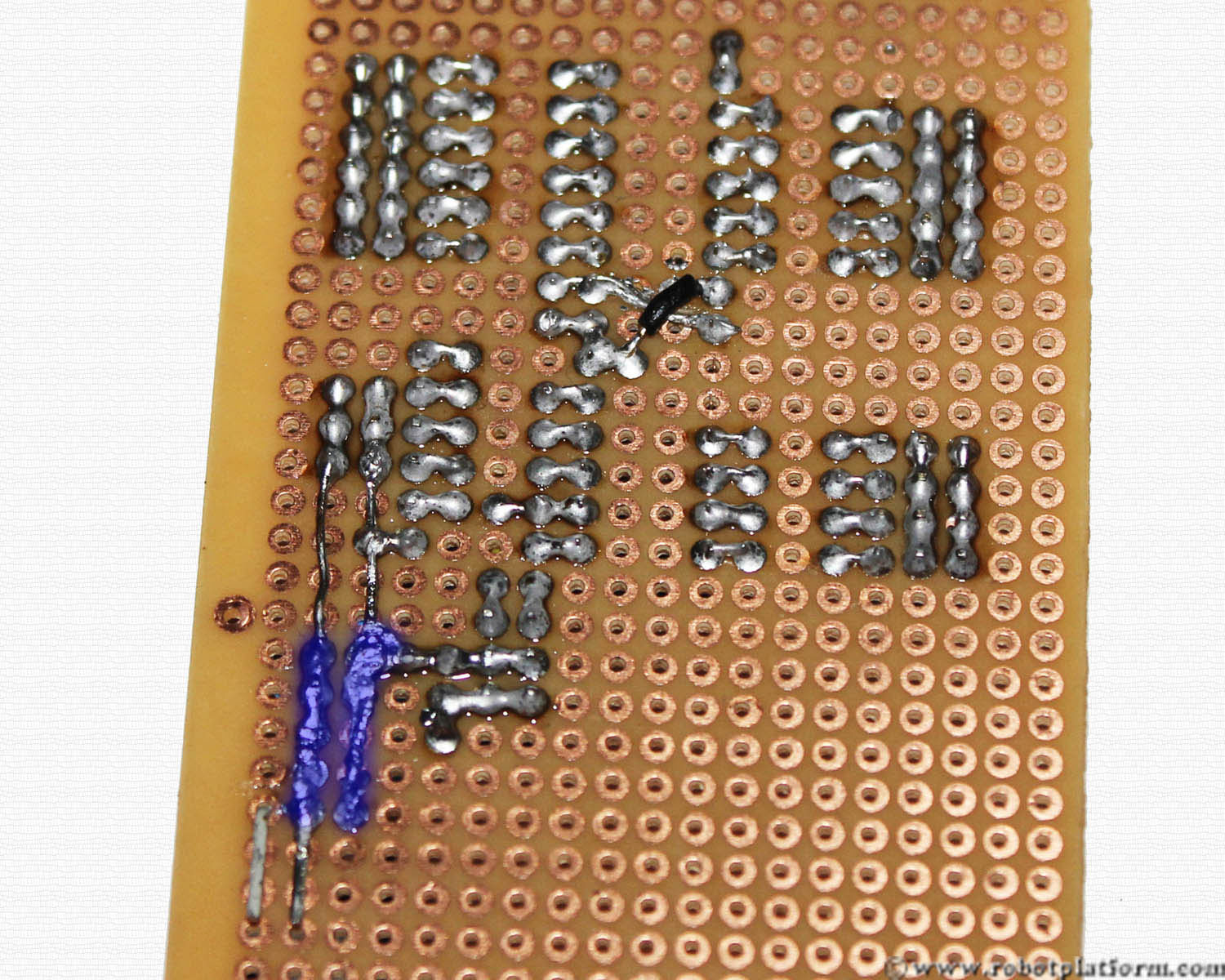
Solder the entire line of pins and wires together as shown in the image
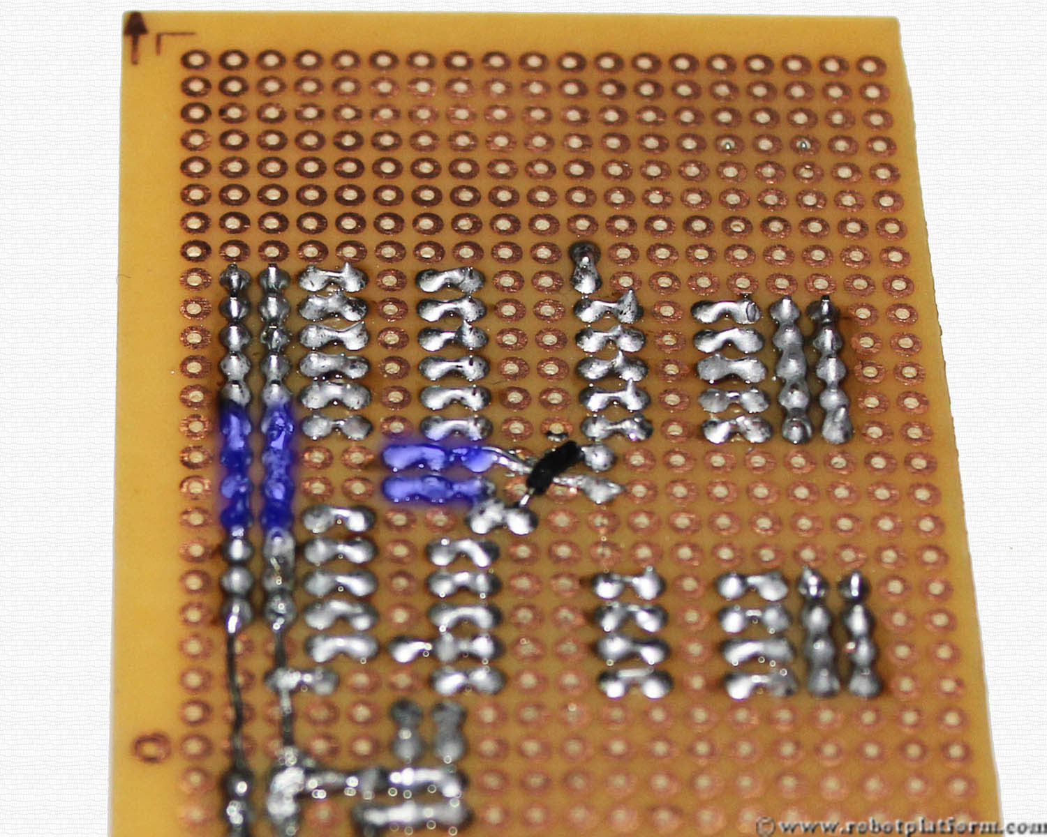
Add two more wires to left side of the board. This connects the ground and power lines of bottom header and top header.
Solder the two wires to the header pins.
Tutorial index:
Do you have anything to say?
Visit the Forum to discuss, learn and share anything related to robotics and electronics !!


