AVR Development board, Step-by-Step-Tutorial
How to build an Atmega8 development board
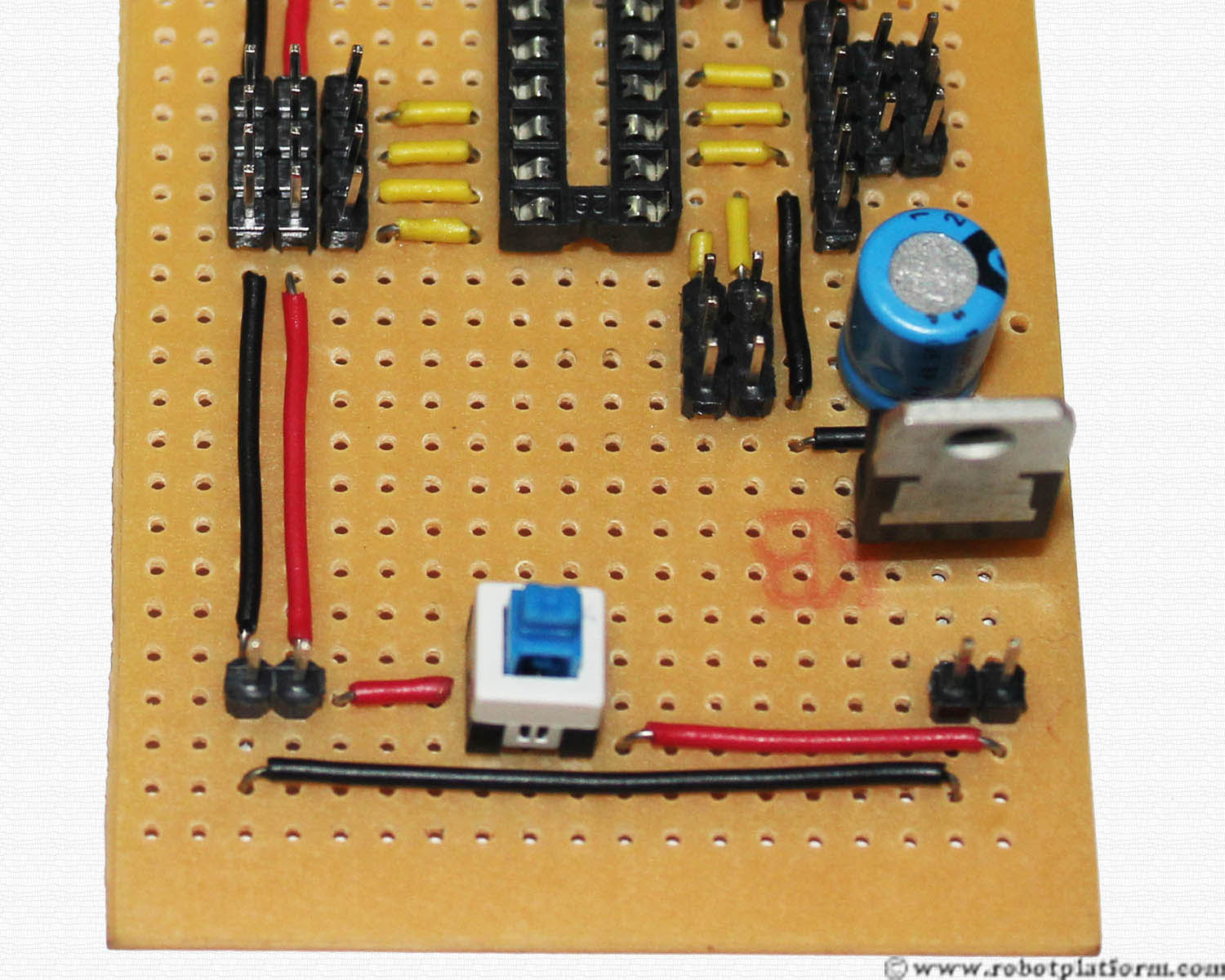
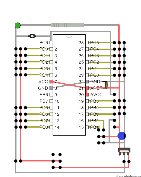
Insert a Push button Switch
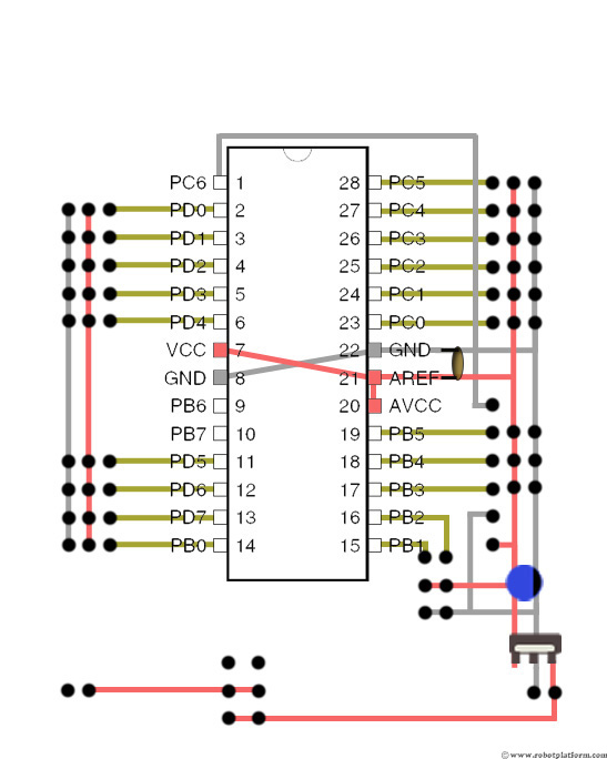
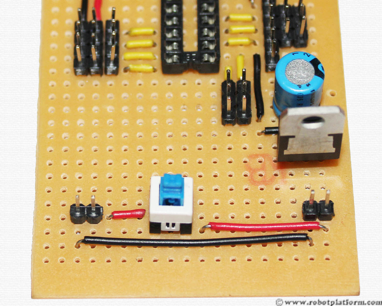
Insert a six pin push button switch (an On/Off switch) to the bottom of the board. Also add a two pin header in the same column as the power and ground lines of left headers.
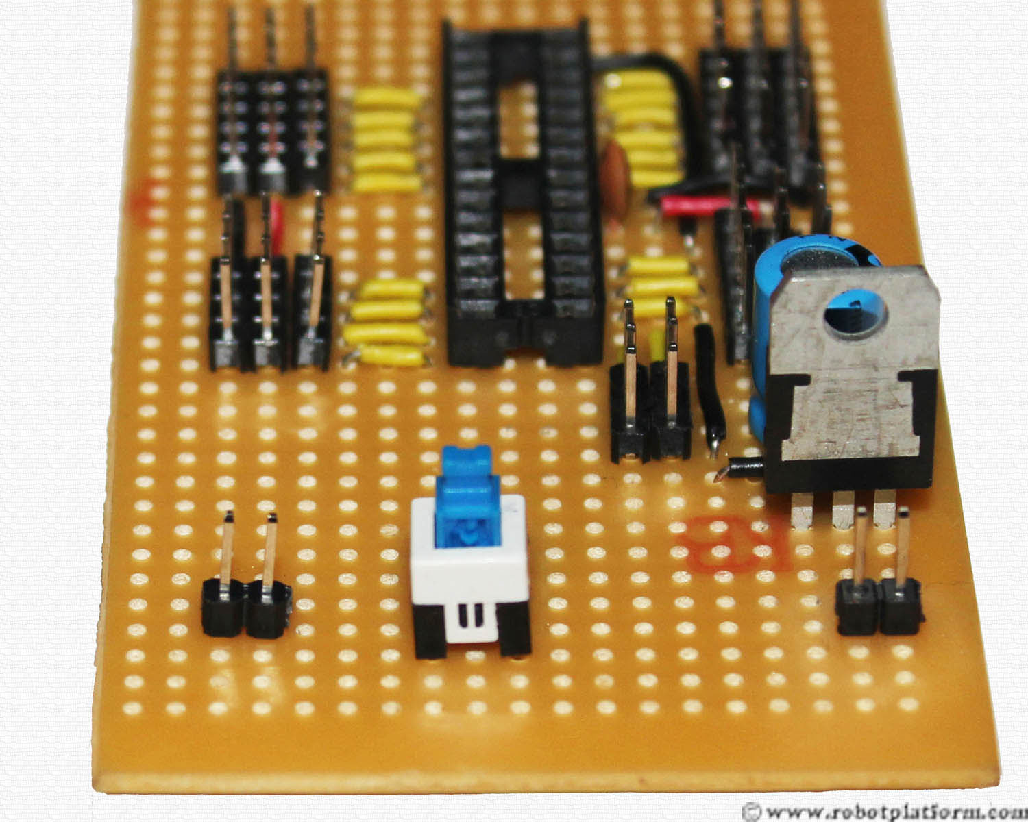
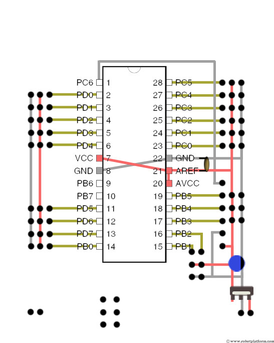
This Switch has six pins which can connect two inputs and outputs. Be careful while inserting the switch as inserting the wrong way may mess up your board. Affix two more red wires; one from power line of battery header to the switch and the other one from switch to another header pin. This switch is used to separate the power lines from left headers to right headers. Once pressed, it connects battery power across both sides of the board. In case you wish to add different source (for motors and servos) then you can add another battery to left header which powers left side of the board.
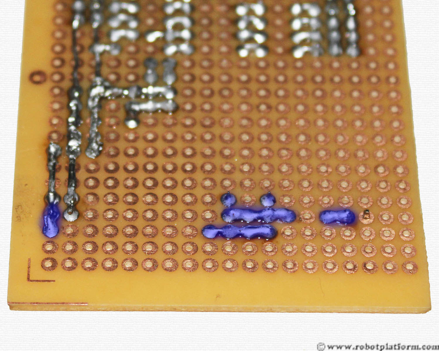
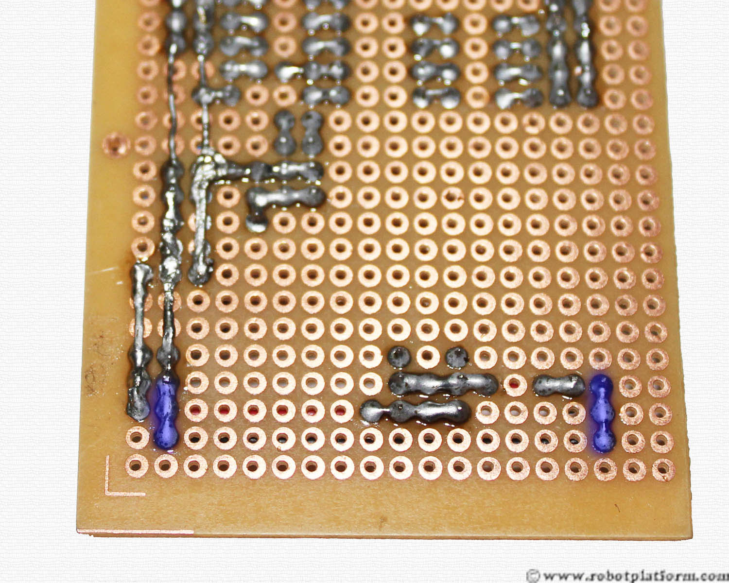
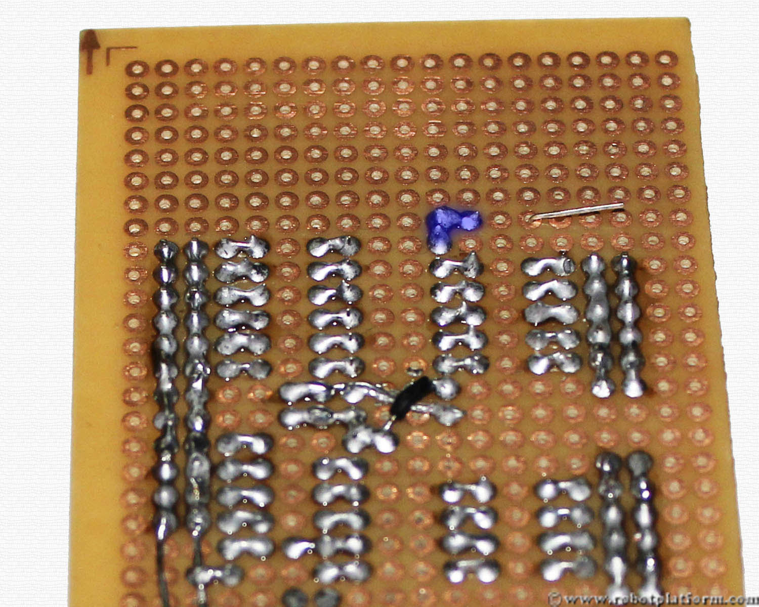
Solder the wires together as shown. The top two pins and the middle two pins of the switch are connected. If the switch is pressed, it shorts the two lines connecting the two battery headers.
The bottom two pins are left unconnected and you can solder those pins to the board to hold it stiff.
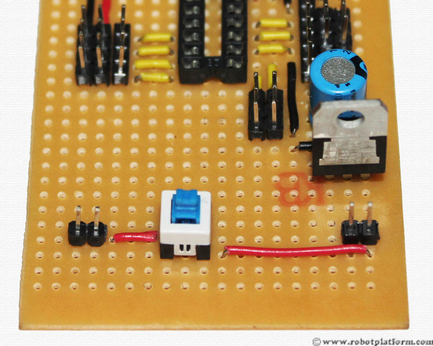
Add one more black wire directly from left header ground to right header ground.
Solder the wire to the headers. The black wire is not connected through the switch as we need the ground lines to be common across the board.
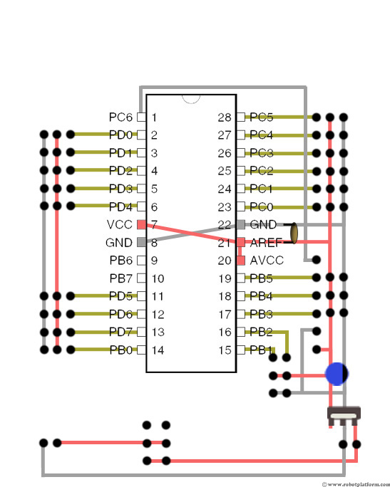
Lastly, connect two more wires, a red and another black wire which connects left headers and left battery header.
Solder the wires to the headers as shown in the image.


This completes the first phase of the board and you have a complete working board ready. In the next section we will add a reset switch to our board.
Reset Switch
We will now add a reset switch to the circuit. In some situations you would need to reset your program without actually pulling off power. A reset switch is a push button switch which resets your circuit when pressed for certain duration. Generally this is available as a two lead switch and if you not lucky enough and find a two pin switch, just check which shorts the leads in the four lead switch and connect accordingly.
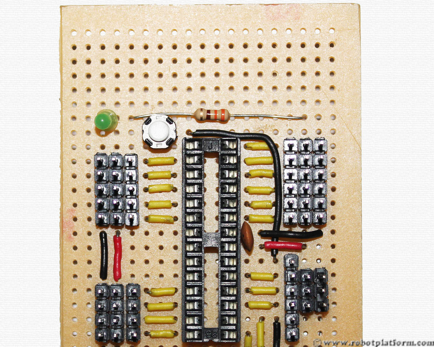
Plug the reset switch such that one lead is close to Pin-1 of the microcontroller and the other with a gap of two pins as shown in the image.
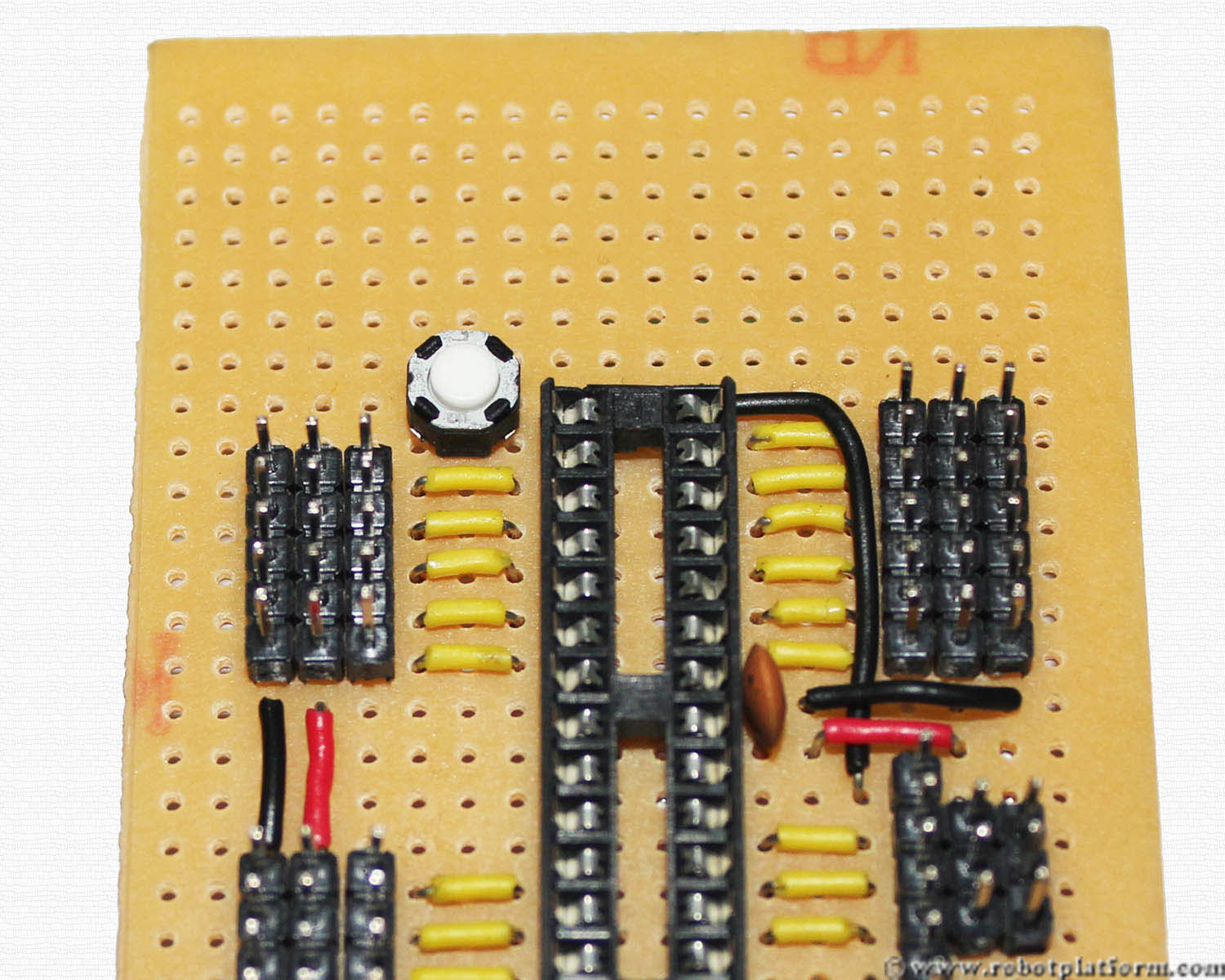
Solder the reset switch lead to pin-1 of the microcontroller. The other pin will be connected to ground, but do not solder it for now.
We will also add a status LED to the board which is useful to check if the circuit is powered on. A current limiting resistor (yes, a normal resistor) of value 330Ω is connected in series with the LED. I have selected a 3mm green LED and you are free to select your favorite color.
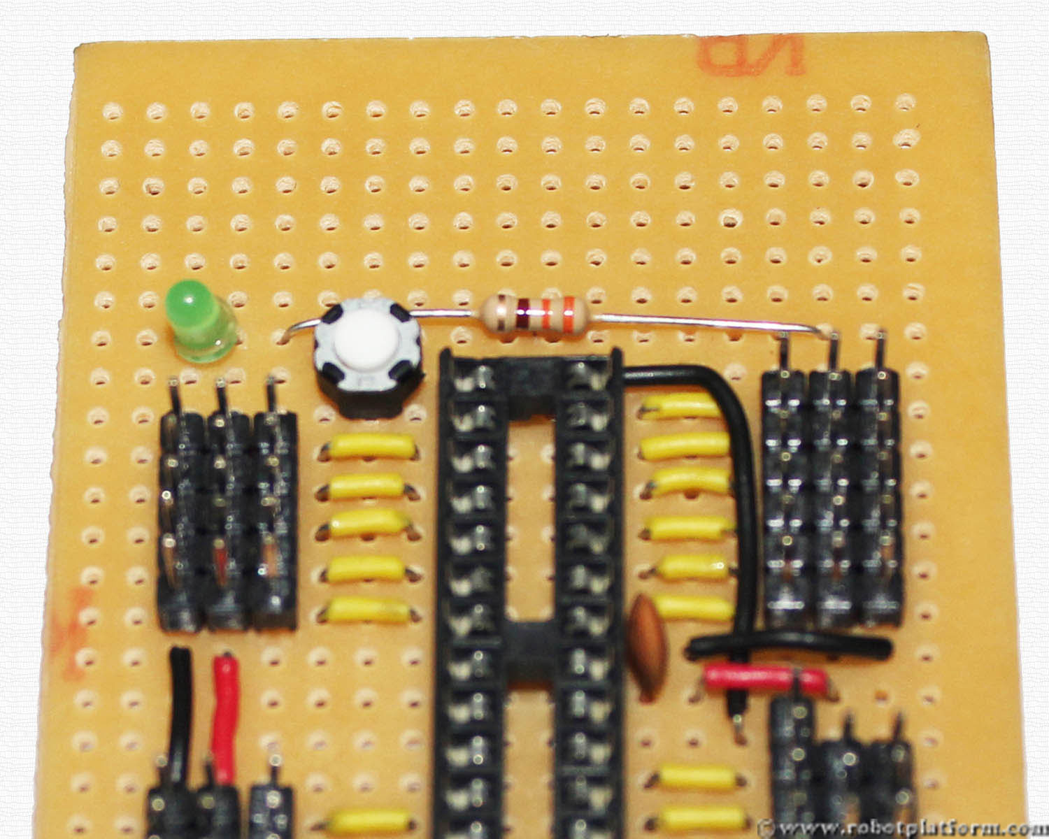

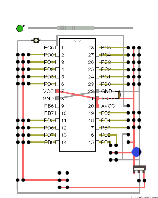
LED has a positive and a negative side. The shorter lead indicates ground, and the longer lead goes to power. Insert the LED such that the ground line is in the same column as the ground line of the header and the longer lead (positive side) is in the same column as the Vcc line of the header (left headers).
One lead of the resistor is plugged into a grid available next to the LED (+ve side) while the other lead of the resistor is plugged into power line of the right headers (refer image).
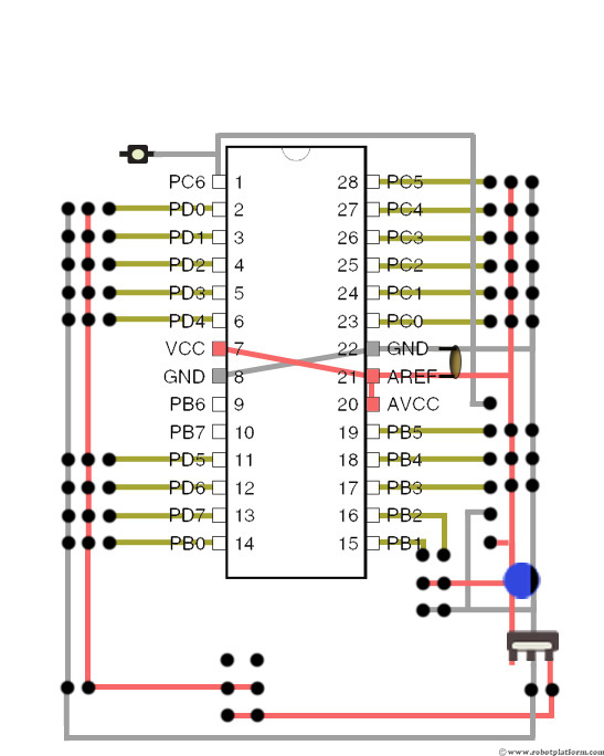
Now follow these steps carefully:
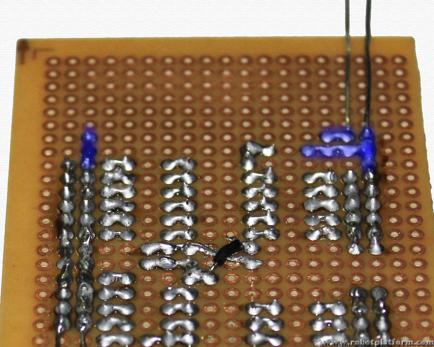
- First solder other end of the reset switch to ground. You can use the reset switch lead to bend and solder it to ground line.
- Now Solder negative side of LED to ground line and positive side to resistor lead
- Bend the other end of resistor such that it is connected to positive line of right side of the board
- Do not trim the LED leads if you would want to go further to add a LCD header. If you think this is enough, trim the LED leads and you have your development board ready.

Congratulations!!! You are done with an Atmega8 development board. Connect your battery to the board and see the green LED light up. Plug in your Atmega8 microcontroller and start programming.
Note: The new microcontroller might resist getting into the socket; you might have to slightly bend the leads and push it in. Be careful not to break the microcontroller pins.
Tutorial index:
Do you have anything to say?
Visit the Forum to discuss, learn and share anything related to robotics and electronics !!


