AVR Development board, Step-by-Step-Tutorial
How to build an Atmega8 development board
Building your first AVR 28-pin development board
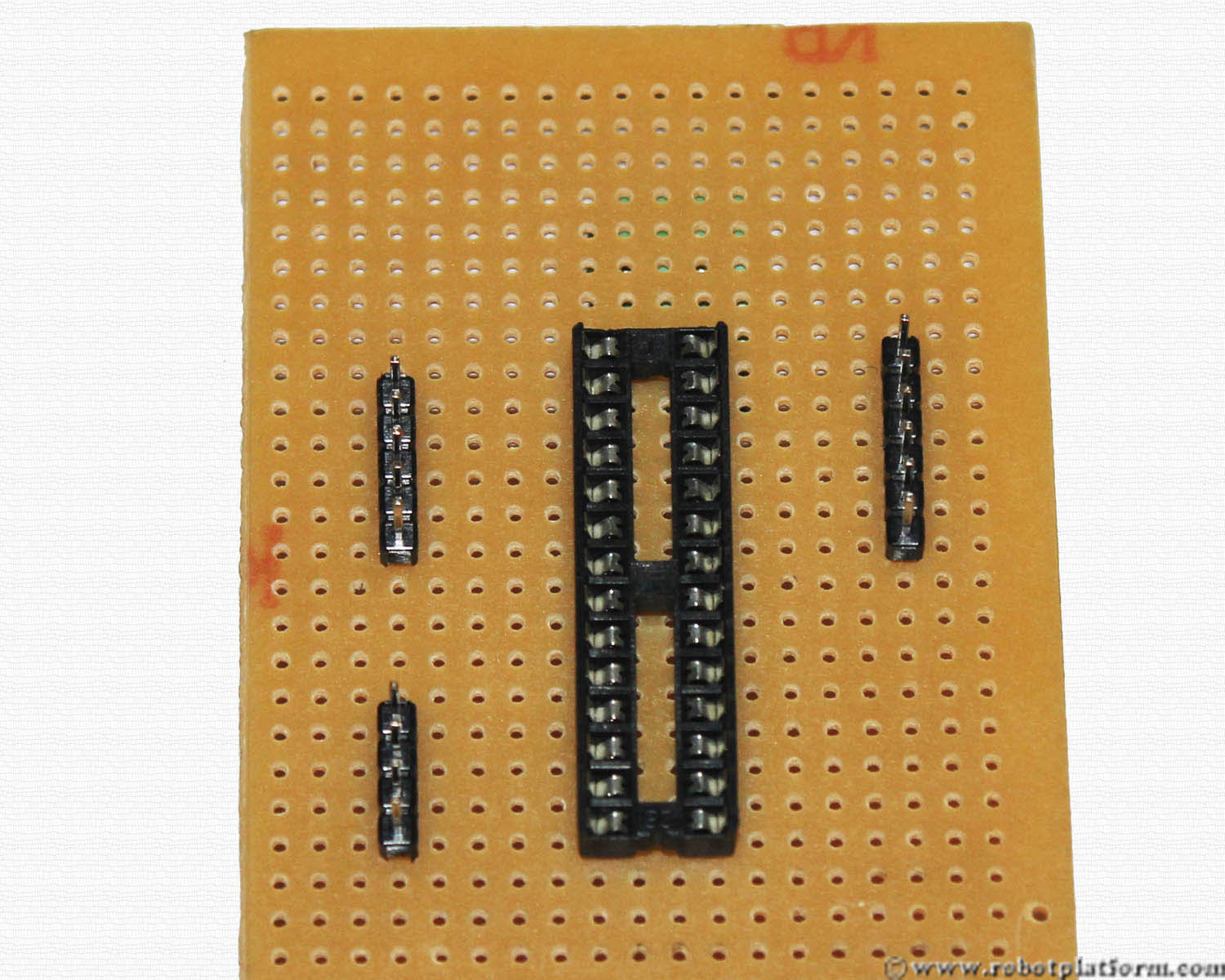
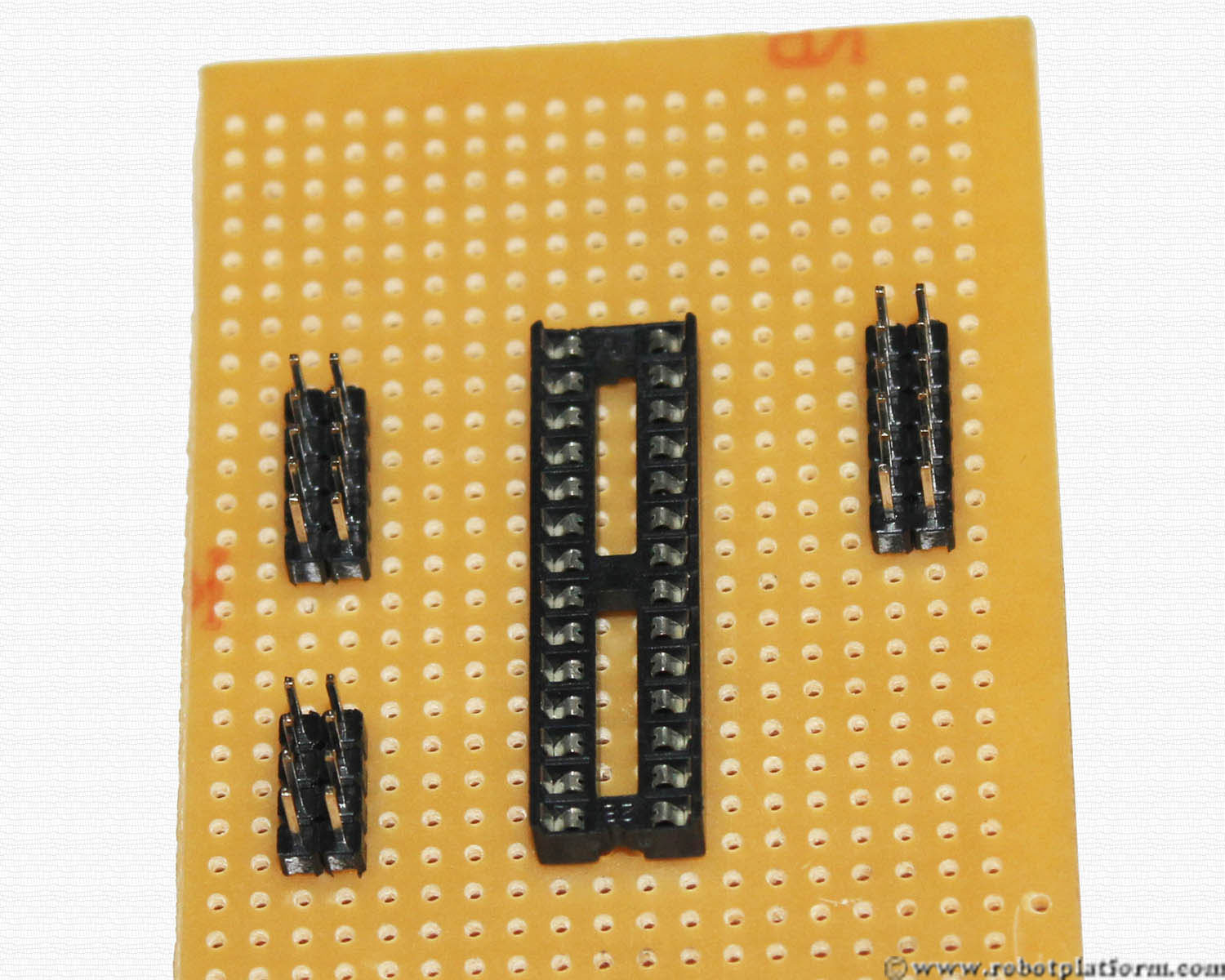
In the image you can see a perforated board and a 28 Pin dip socket. Place the socket as shown in the image, but do not insert the microcontroller until you have completed with the entire board; just hold your excitement for a while.

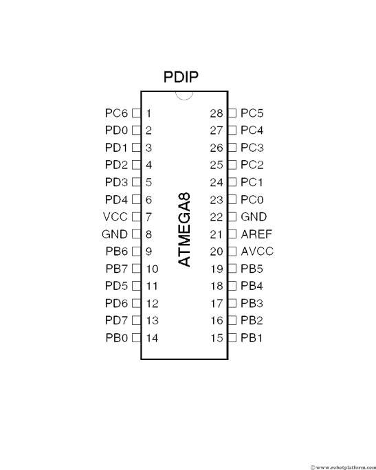
If you are lucky enough to find a board with letters and numbers along the columns (sequence of vertical grids) and rows, (sequence of horizontal grids) then use that as a guide. I have virtually added pin numbers for the socket in the first image. The pin in the left top corner is PIN-1; Count downwards and then continue from bottom-right. The top-right corner pin is PIN-28. (Atmega8 microcontroller is numbered in a similar fashion)
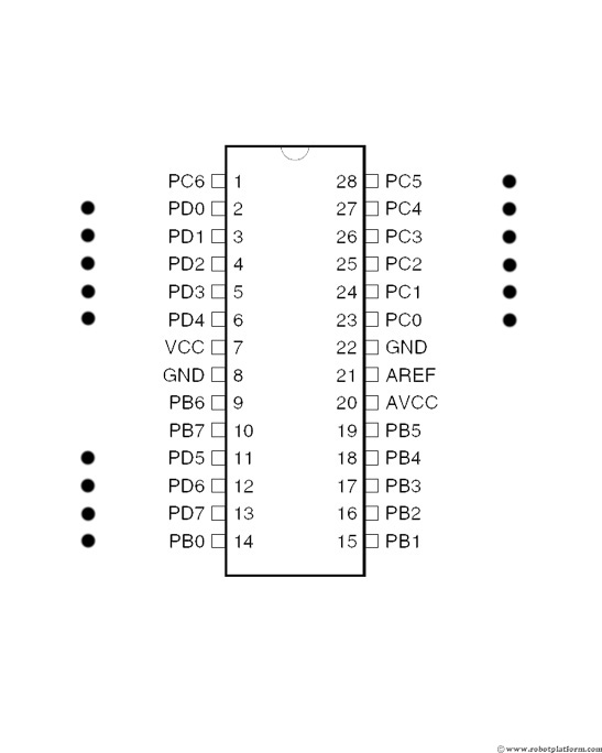
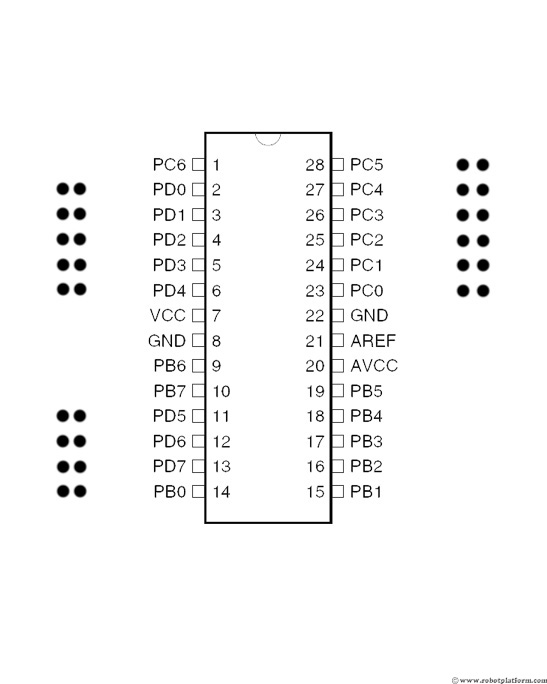
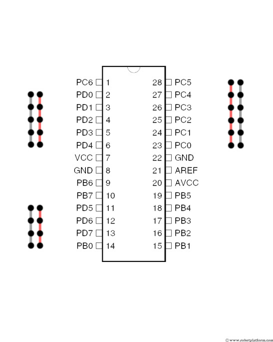
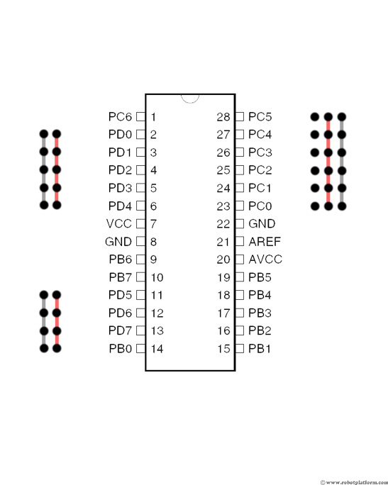
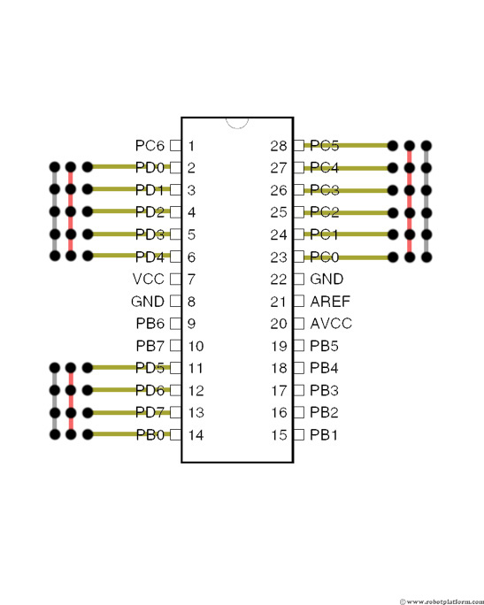
To give you a clearer picture, I have added a schematic builder (yeah, I came up with this word), which is an Atmega8 microcontroller image and its pins; as you read the tutorial, I add colored lines to indicate connections and make you feel more comfortable and confident.
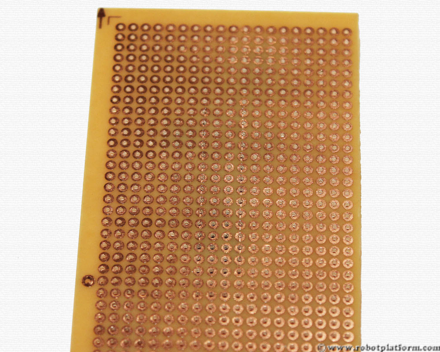
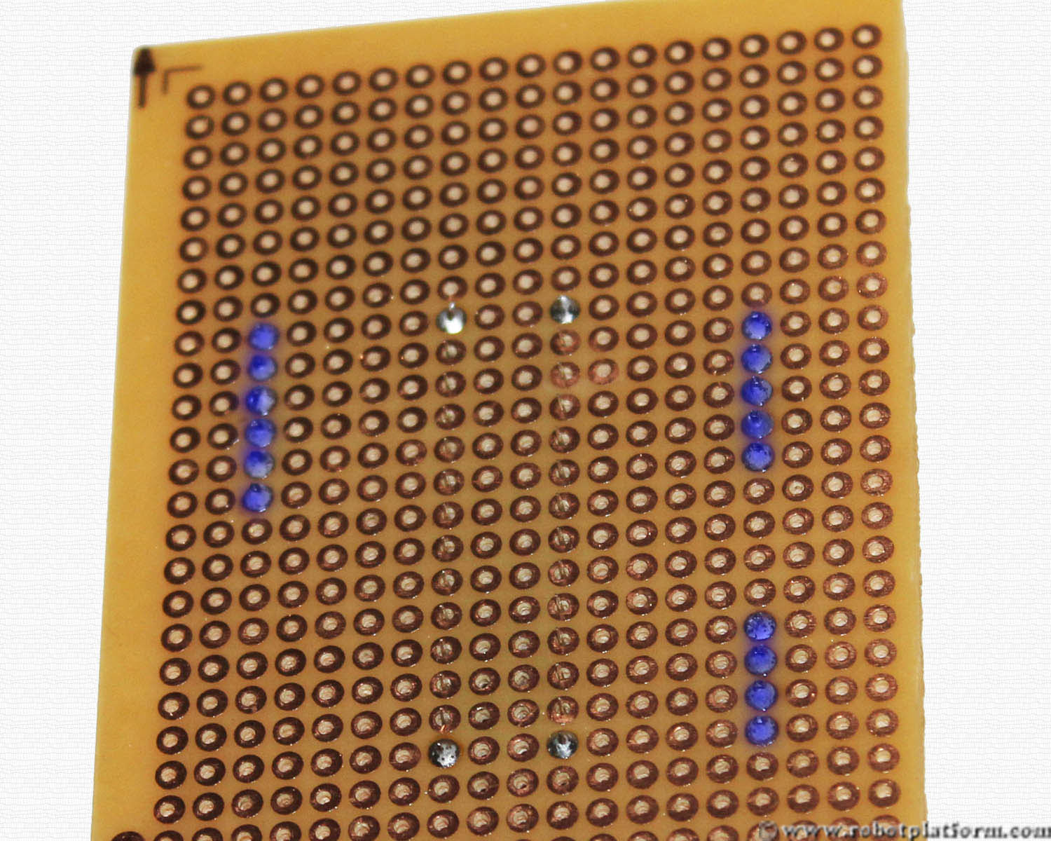
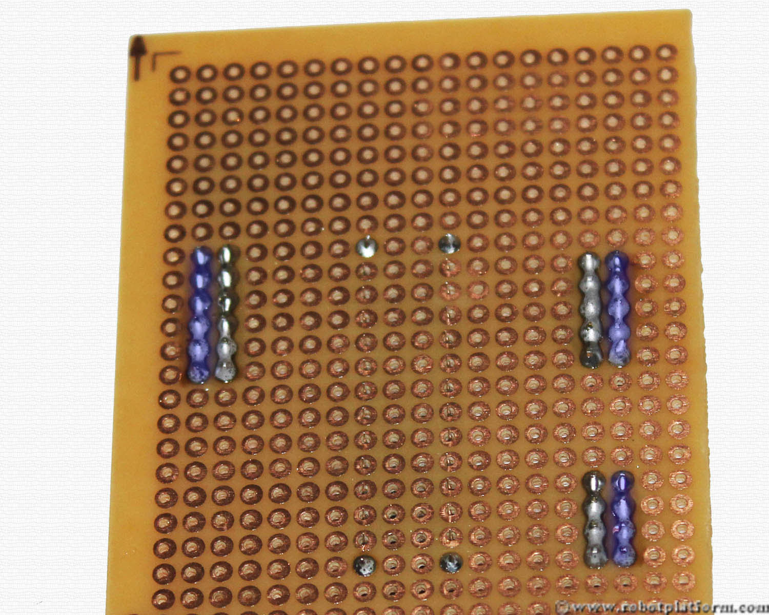
Turn the board to the other side and you see the perforated board with copper layers around each hole. This is generally known as Copper side of the board where you solder the pins and component leads. You can also see the leads of 28 pin DIP socket in this image.
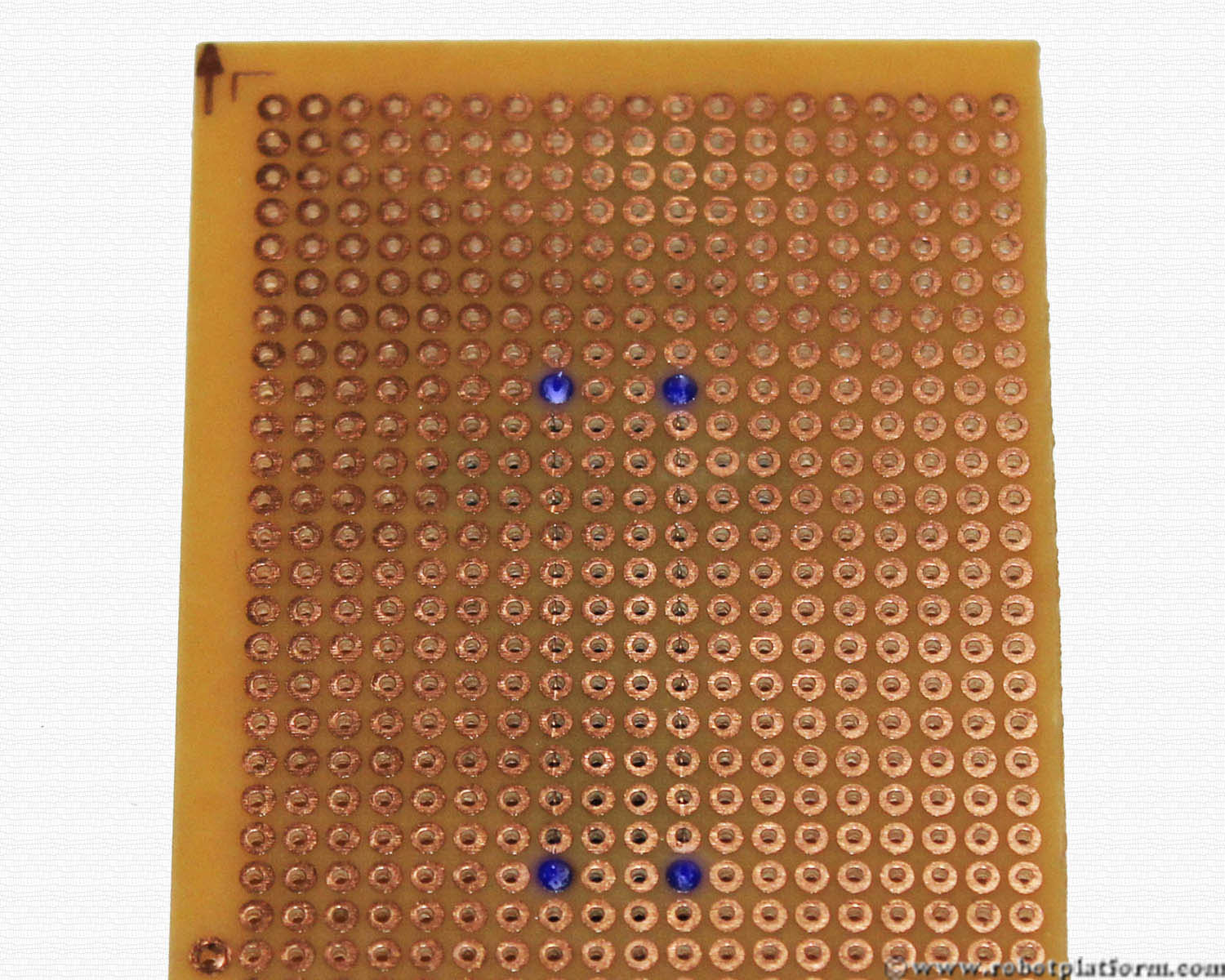
Solder the four corners of the socket as shown in the image. If this is the first time you are soldering, you may not have acceptable results. To avoid that, find a circuit board in an old radio and try practicing how to solder.
Soldering tips:
- Get a good solder iron and solder (also known as solder lead) from your local radio shop. Temperature controlled solder iron is also available. However it is not really required to use that for this simple board, but worth investing on a decent one
- Always heat the leads of components first and touch the solder to the component leads. Never touch the solder directly to the iron
- Once you are done, place the iron back into the stand
- Keep a damp sponge or a thick wet cotton cloth and clean the iron tip frequently
- If you ever overdo the soldering, use a solder wick to remove excess solder
- Flux can be used to ease soldering process. It removes oxidation from metals and increases connectivity. Most solders have flux inside them, but if you ever need more flux, get a small box (also available in the form of pen, tin etc)
- Lastly, if you can solder better than me, deem that I am learning. If you are worse, don’t worry, you are still learning.
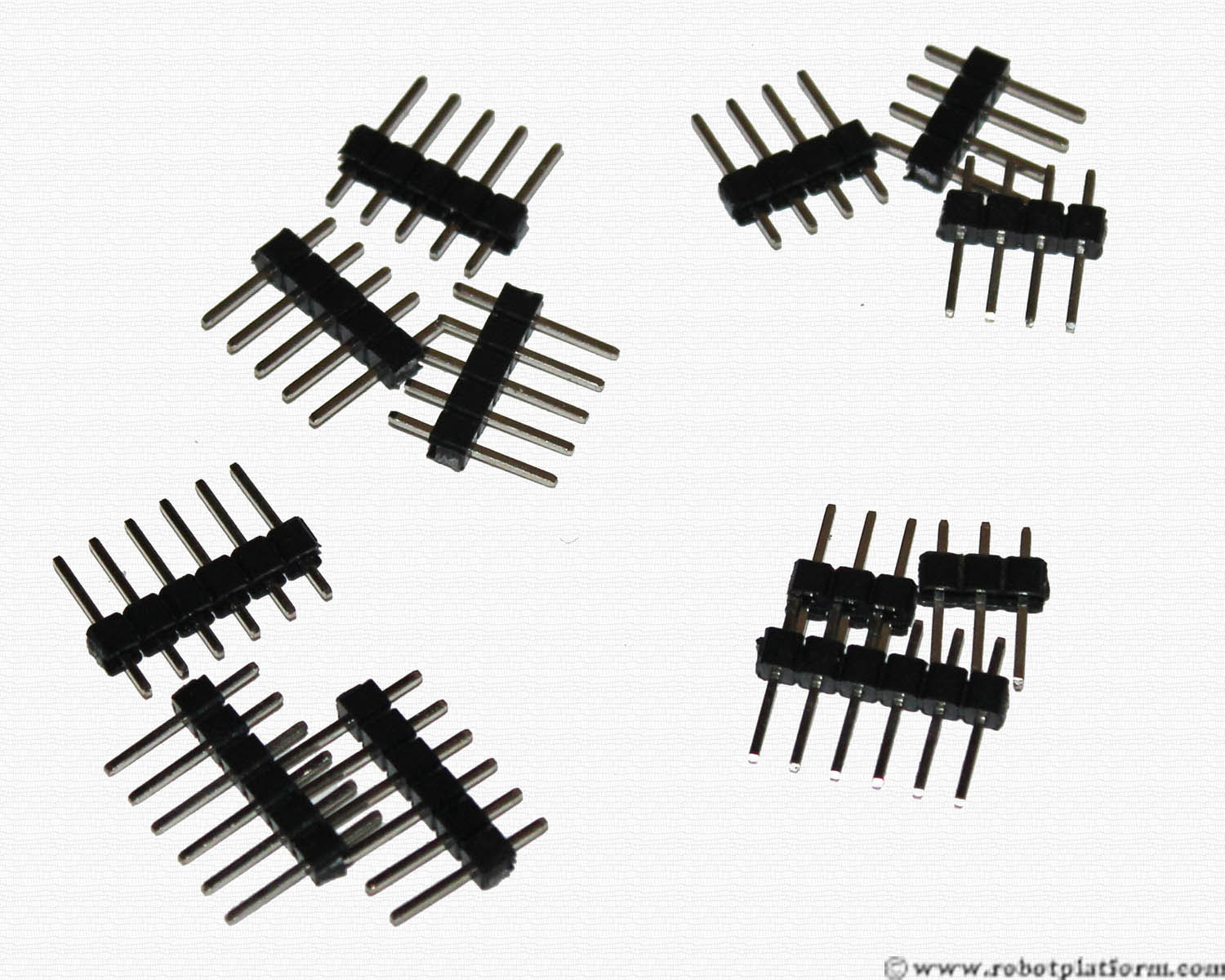
Get your 40 pin male header and break them into smaller pieces. These headers act as connectors to external peripherals like programmer, motor, LED etc. The headers breakaway easily with your fingers;
Break and arrange the male headers as stated below:
- 3 x 4 pin headers (Three headers, each header with 4 pins)
- 3 x 5 pin headers (Three headers, each header with 5 pins)
- 4 x 6 pin headers (Four headers, each header with 6 pins)
- 2 x 3 pin headers (Two headers, each header with 3 pins)
Now carefully add three headers to the board. The first pin of the first header (5-pin header) goes to PIN-2 of the socket. The first pin of the second header (4-pin header) goes to PIN-11 of the socket. The first pin of the third header (6 pin header) goes to PIN-28 of the socket. Make sure that there is a gap of 4 columns between the headers and socket (you will understand later why there is a gap of 4 columns).
Also, the first pin of the socket is the reset pin and does not have a header; we will later connect this pin to reset line.
Note: For those who would like to save this pin, you can still add a header to this line and use reset pin as an I/O pin, but you need to program RSTDISBL fuse and handle a lot of complications. Better be it as reset pin, as used in this board.
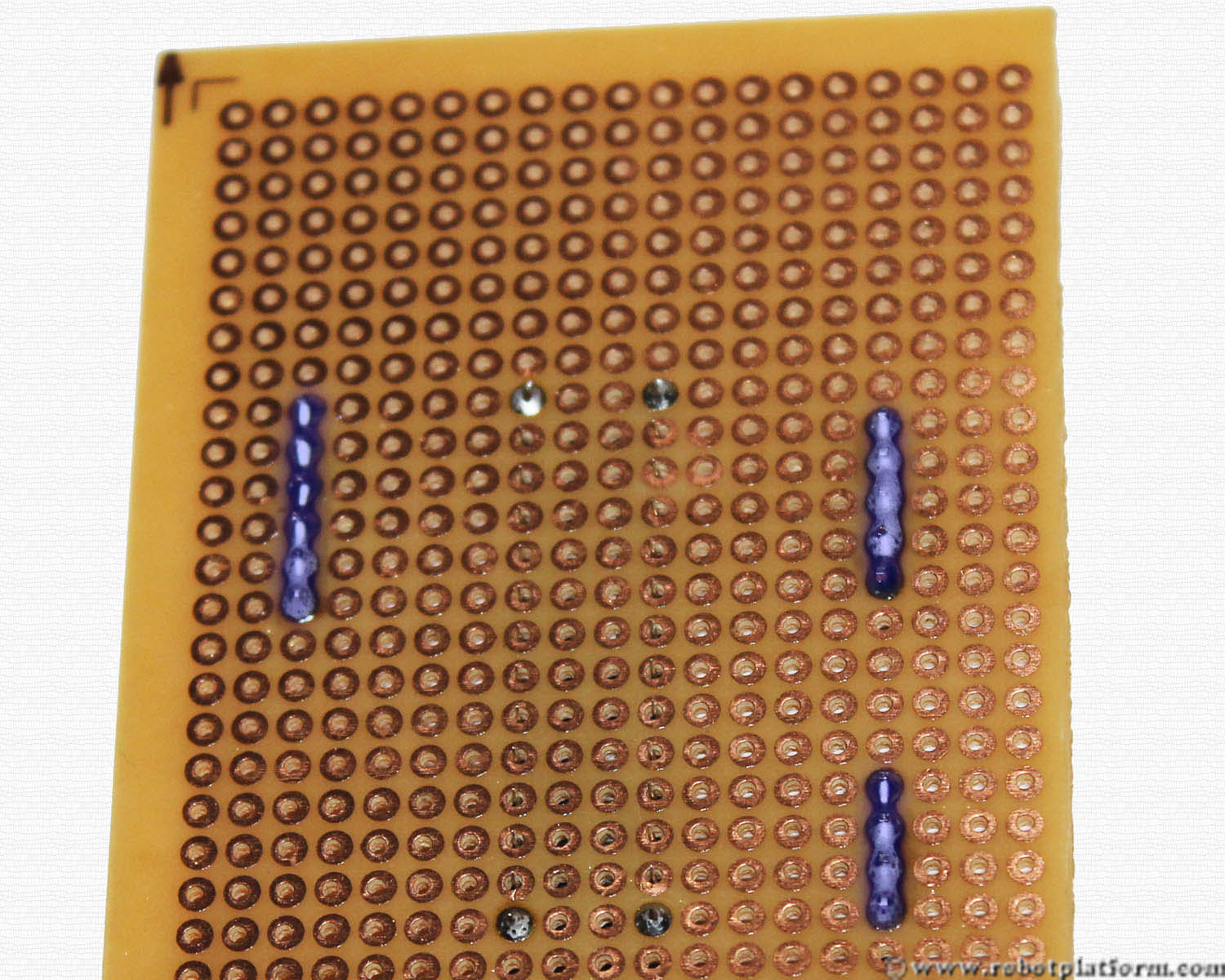
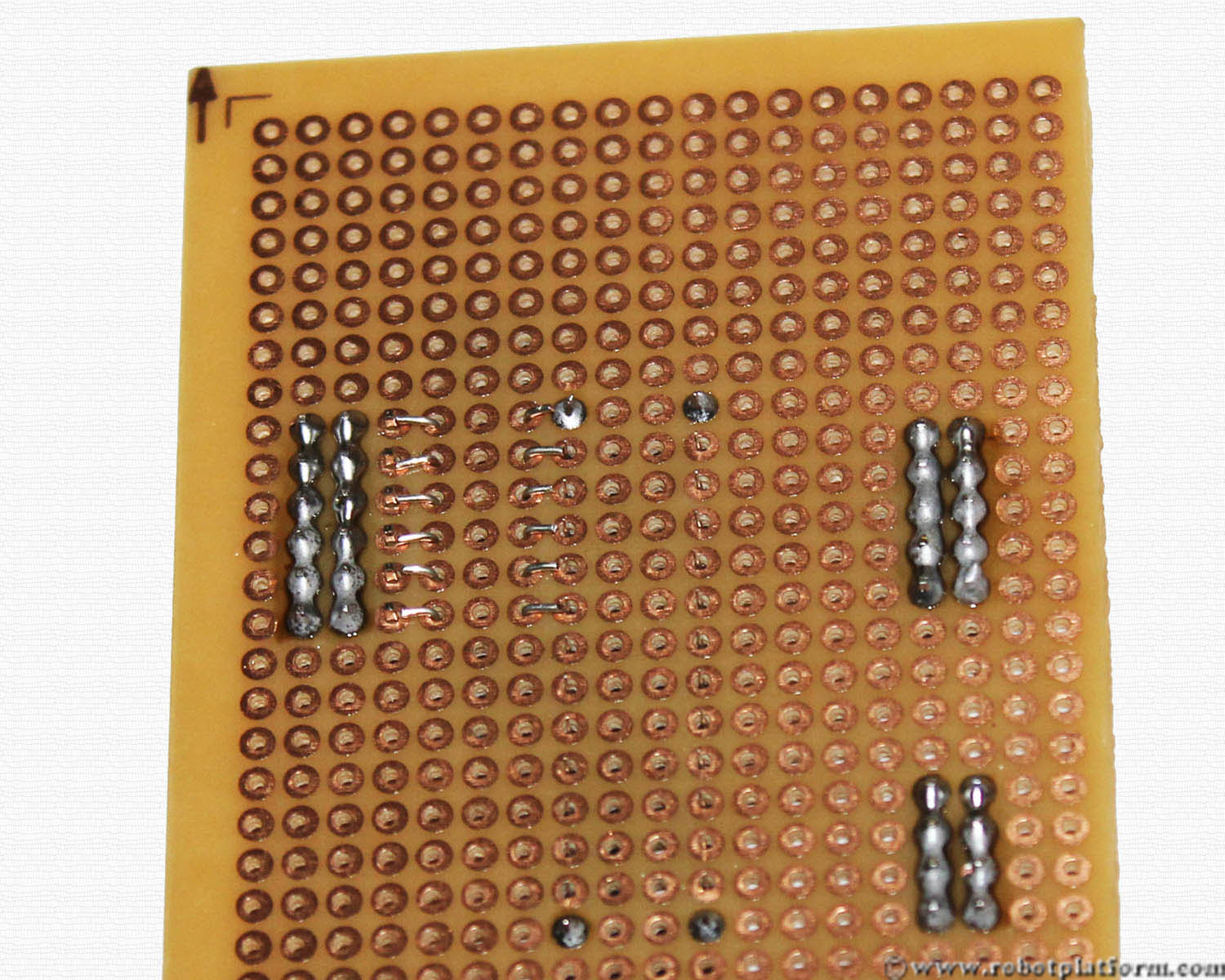
Flip the board and solder the individual pins of each header together. As you can see in the image, I have first soldered individual pins to the copper pad and then connected them together. These lines are later connected to power (+ve of the battery) and act as a bus which supplies power across the board.
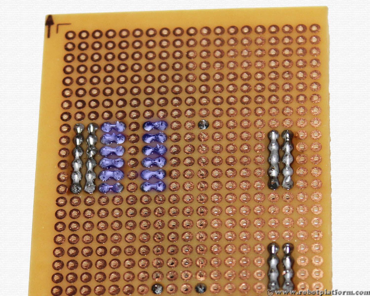
Now place another set of similar headers next to existing headers. Insert a 4-pin header and a 5-pin header towards the left of existing ones and 6-pin header towards the right side of existing header. These headers will be later connected to ground (-ve of the battery).
Solder the ground lines together as shown in the image. Do not short the power lines and ground lines; if you have a Multimeter, check for connectivity and remove and re-solder if you have accidently soldered ground and power bus lines using solder wick.
Now it is time to add more headers for signal lines (call it I/O lines, control lines or whatever, but understand what they are used for). These header pins are directly connected to the 28-Pin socket (which means, directly to the microcontroller pins) and acts as a connection between the microcontroller and the external world.
Pull out, cut and strip the wire you bought and bend them as shown in the image. The wire length should be approximately equal to length of three holes of your Perfboard. This is a bit of art and you really need to take time to cut and bend the wire perfectly. If you have three different colored wires, spare the red and black wires and use the third colored wire (yellow, orange or white).
Tip: Although multi-strand wires are easier to solder, it is superior to use a single strand wire for your board as the multi-strand wires stray and may short the connections.
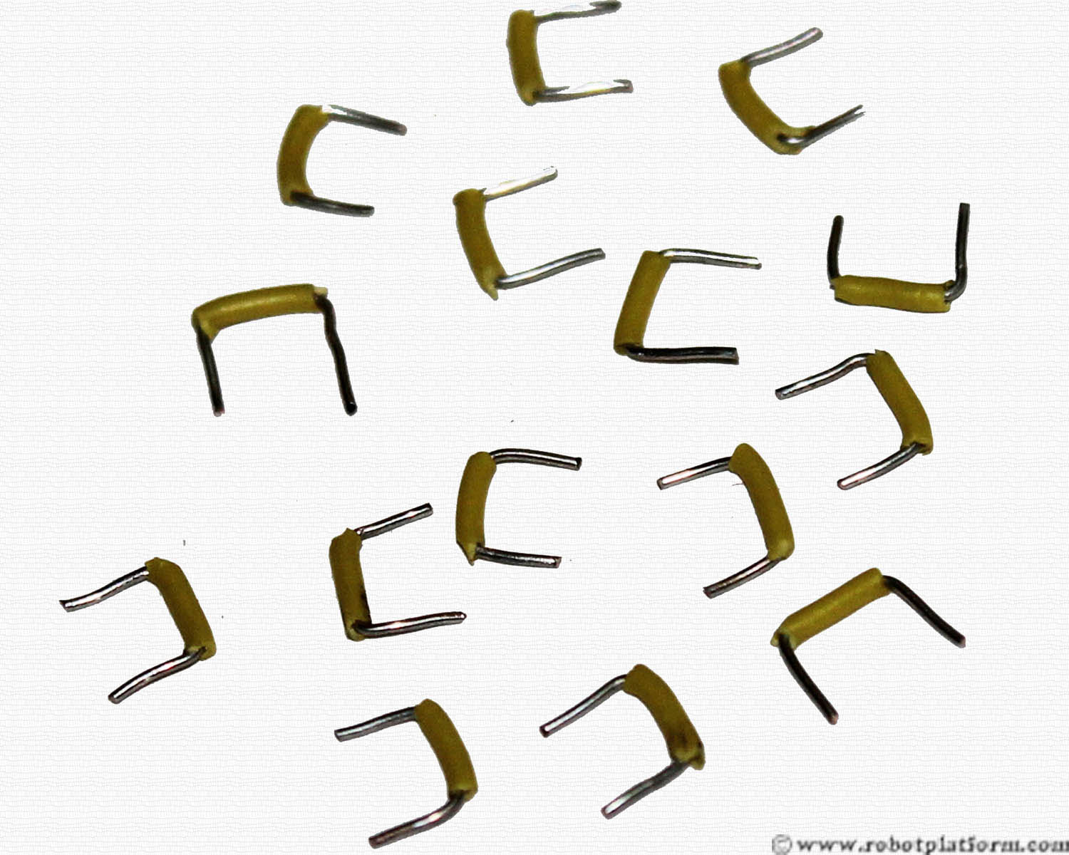
Make atleast 20 of them and if it took more than few minutes to cut these wires, take a break and come back :)
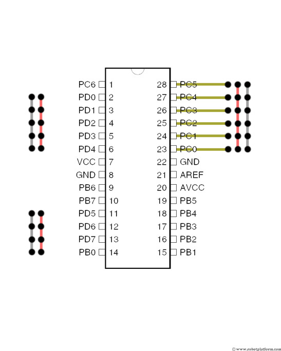
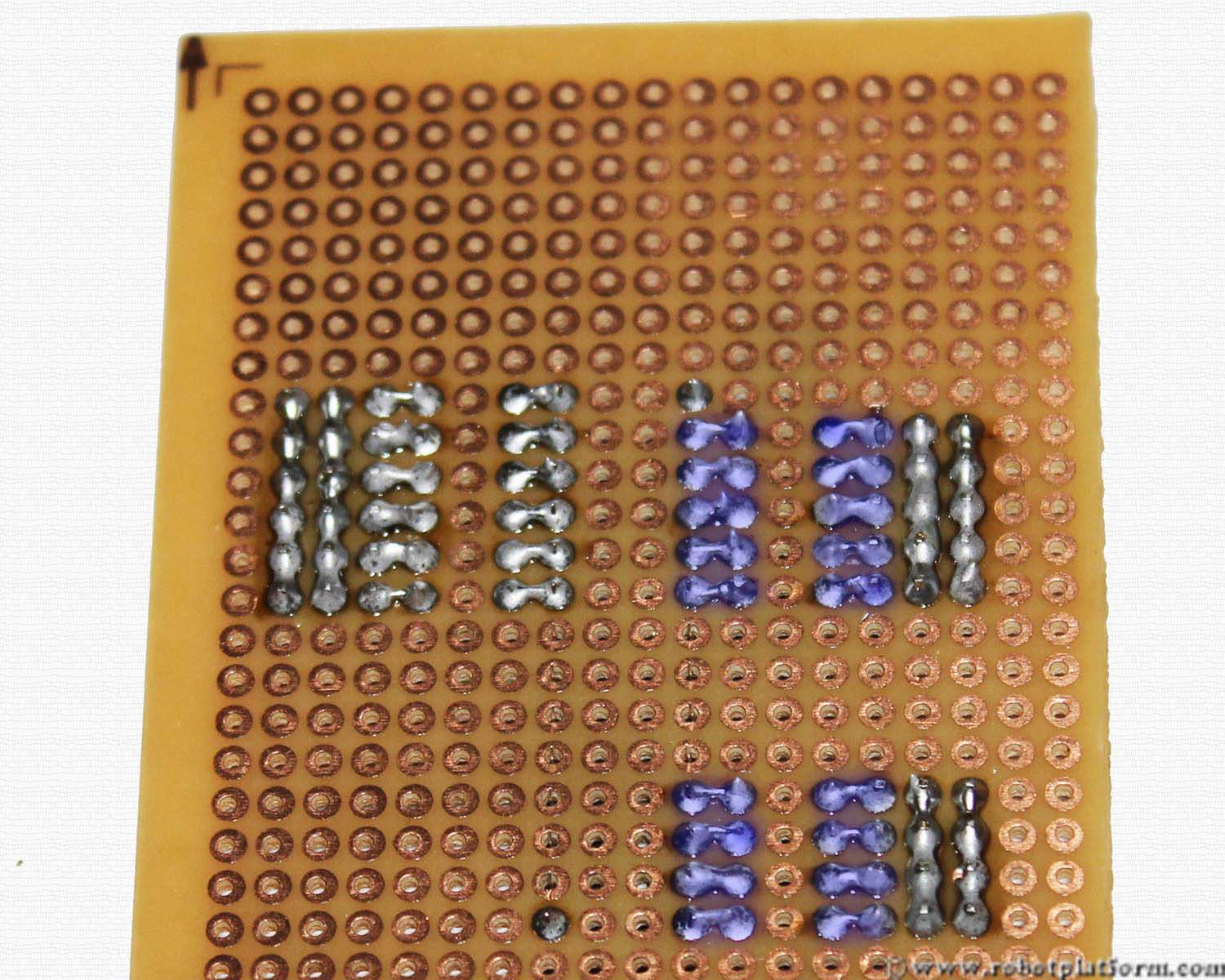
We will add headers for signal lines one by one. On the right side of the board, there are two headers with 6 pins in each. Add one more 6 pin header to the left of it.

Carefully insert the wires you just cut, into the holes as shown in the image. Each wire should connect a header pin to the respective socket pin (the socket pin in the same row).
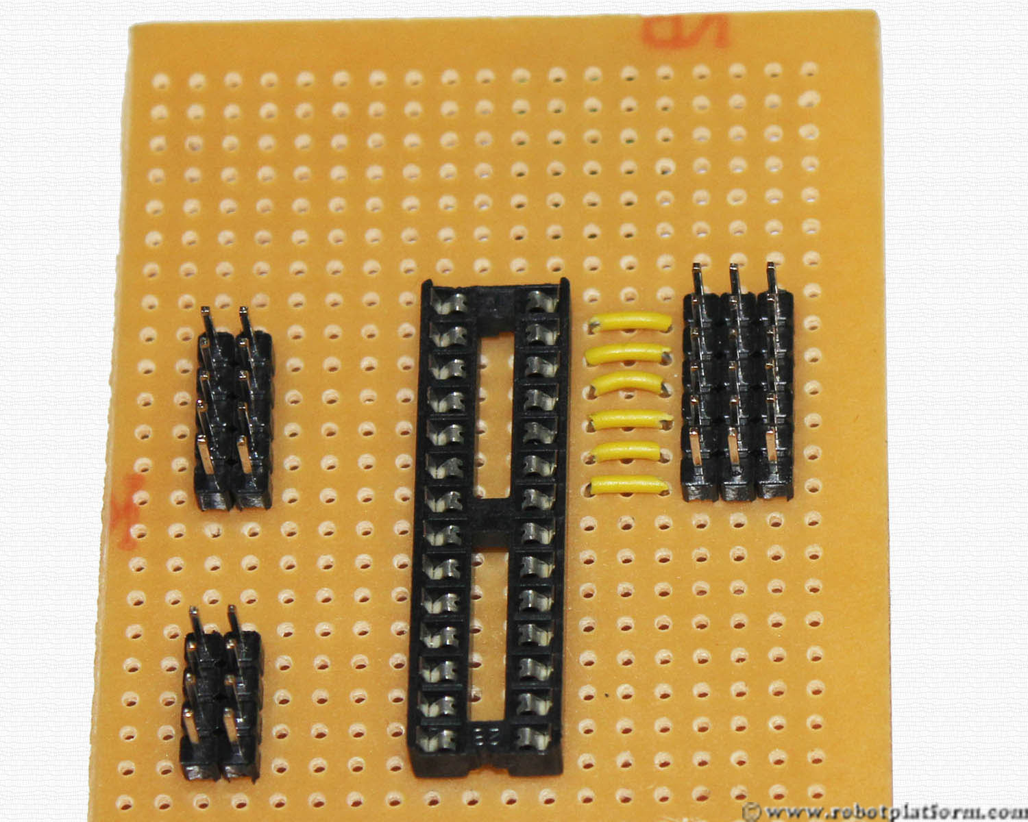
Bend the wire edges as shown in the image. This is to make your soldering process easier while holding the wires in place.
If the solder iron is still on, wipe it over a damp sponge and clean the tip. Solder each wire to the header pin and further to the socket pin. Do not short the header pins, or the socket pins to each other. Solder it exactly as shown in the image. If you successfully complete this step, then rest of soldering is cheese.
Similar to the right side, add headers to the left side of the board where there are already two headers. Add the same number of headers to the right side of existing headers and insert wires between the header and the socket. (5 pin and 4 pin headers)

If you have already guessed it, then yes, we will repeat the same process followed (i.e, while adding previous signal header). Carefully solder the socket pins to the header pins one after the other. As mentioned before, do not short the header pins to each other, or the socket pins to each other.
Tutorial index:
Do you have anything to say?
Visit the Forum to discuss, learn and share anything related to robotics and electronics !!


